
ANSI Transformer Standards for Lead Identification
To eliminate confusion about how to connect transformers, the American National Standards Institute (ANSI) has established standards for marking the connections to transformer coils. The transformer coils are usually called windings, and the wires that connect to the windings are called the leads.
Transformer H and X lead identification
ANSI standards require that the leads connected to high-voltage windings be marked with an H and leads connected to the low-voltage windings be marked with an X. The standards do not refer to primary or secondary windings because either the H or the X windings can be the primary winding. If the transformer steps up the voltage, the primary winding (the winding to which voltage is applied) is the low-voltage, or X, winding. If the transformer steps down the voltage, the primary winding (the winding to which voltage is applied) is the high-voltage, or H, winding.
Transformer lead identification for transformers with one or more windings
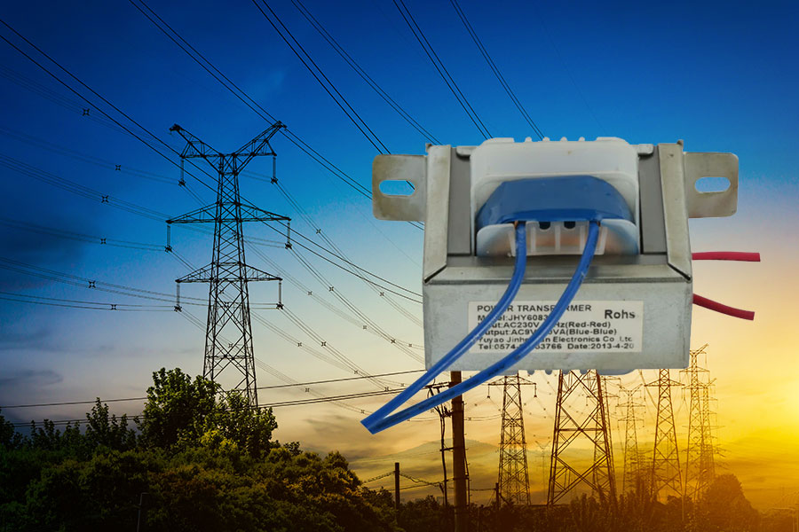
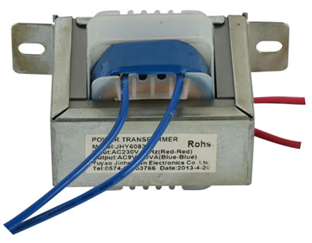
The ends of the windings are given numbers to indicate the start and end of each winding. Thus, an H winding has two leads: H1 and H2. An X winding also has two leads: X1 and X2. If a transformer has more than one high- or low-voltage winding, the lead numbers of the second windings would be H3 and H4 as well as X3 and X4, respectively. Now since the turns ratio is equal to the voltage ratio, the H winding will always have more turns than the X winding because the H winding is always the high-voltage winding. A typical single-phase transformer is shown in Figure 1.
Figure 1. A single-phase transformer showing how winding leads are brought out to allow for connection to supply and load:
Transformer lead polarity and lead identification numbers
The ANSI standards also determine which end of each winding should be labeled as a 1 or a 2. If we think about the direction of current flow through the winding, we could consider one end of each winding the start and the other end the finish. Current will flow from the start of the winding to the finish, which means that the start of each winding has a definite polarity. Because transformers are only used with AC voltages, the direction of current through the coil is constantly changing; at any point in time, however, one side of the winding will have a positive polarity, whereas the other side of the winding will have a negative polarity. ANSI standards require that each winding lead that is marked with an even number should have the same polarity at any instant in time as any other winding lead marked with an even number. If a winding lead is marked with an H2 and it is positive at some point in time, then any winding lead marked with a 4 will also be positive at that same point in time because it also has an even number. Figure 2 shows the instantaneous polarities of a transformer and the resulting lead identification.
Figure 2. Transformer windings labeled according to ANSI standards, with the same polarity leads having the same even or odd numbers:
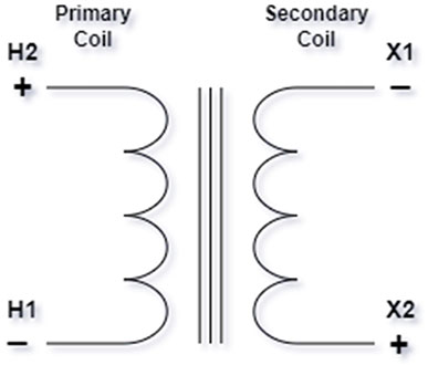
Figure 3 shows the symbol for a transformer. If you look at the symbol, it should be clear that we can show the leads of the high- and low-voltage windings arranged in relation to each other in two different ways.
Figure 3. The symbol for a transformer:
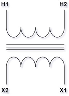
Figure 4 shows a transformer symbol with the H1 lead directly across from the X1 lead on the left and a transformer symbol with the H1 lead directly across from the X2 lead on the right.
Figure 4. Transformer symbols for additive and subtractive polarity transformers:
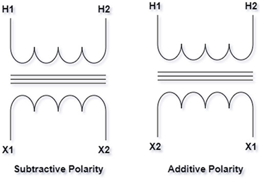
Subtractive polarity transformer winding configuration
The term subtractive refers to the fact that if we supplied voltage to the H1–H2 winding of the transformer and connected together the X and H leads that are on the same side of the transformer (the H2 lead to the X2 lead, for example), we will read a voltage less than the applied voltage between the remaining high- and low-voltage leads (H1 and X1). Figure 5 shows this connection and the polarity of the coil voltages.
Figure 5. A subtractive polarity transformer showing the opposition of H coil and X coil voltages:
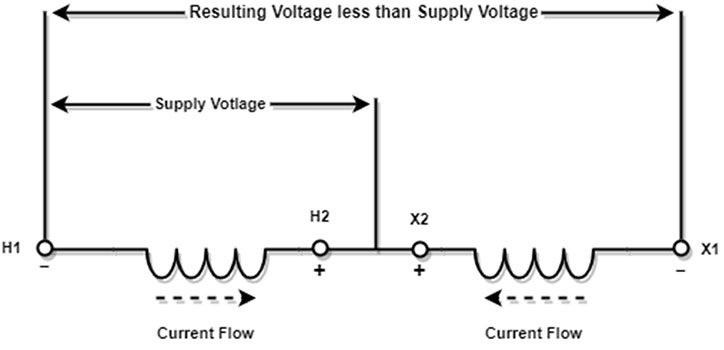
The magnetic flux of the H1 and X1 leads oppose each other because both leads have the same polarity. As a result, the voltage stress between the leads is less. This is important if both leads leave the transformer case through the same opening or on the same side when the rated voltage of the transformer is high or the power rating of the transformer is very high. The ANSI standards require this subtractive configuration of the transformer leads if a transformer has a voltage rating over 9,000 volts or a power rating over 200 KVA; all other transformers will have the H1 and X2 leads on the same side or next to each other as they leave the transformer case.
Additive polarity transformer winding configuration
A transformer with the windings arranged as shown in Figure 6 will have the flux in the H1 lead aided by the flux in the X2 lead, but because the voltage and power of the transformer are lower, the voltage stresses are not as significant.
Figure 6. An additive polarity transformer showing how the H coil and X coil voltages add together:
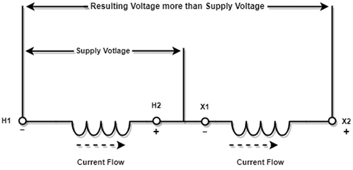
The transformer with leads configured this way is called an additive polarity transformer. This is because if we supply voltage to the H1–H2 winding of the transformer and connect together the H and X leads next to each other, we will read a voltage more than the applied voltage between the remaining H and X leads: H1 and X2.
It is important to note that the voltage and turns ratios of the two different connections are the same. The only difference between the two connections is the way in which the leads are brought out of the transformer enclosure and the way in which we draw the transformer symbols. Almost all transformers that you will work on as an electrician will be additive polarity transformers. The subtractive polarity transformer connections will be found in substations or utility transformers that are usually serviced by electrical line people.