
Application and Purpose of Grounding Transformer
Why are grounding transformers needed?
It is very important to properly ground different power system components because doing so improves their availability, basic insulation level, overvoltage tolerance, and short circuit withstand capabilities. However, certain parts of the system may not have the required neutral connection for grounding and thus require a second component, like a grounding transformer, to install the required grounding capability.
Grounding transformers provide grounded neutral connections for ungrounded three-phase systems, e.g., delta-connected and ungrounded wye systems. If a single line-to-ground fault occurs on such an isolated or ungrounded three-phase system, the zero-sequence fault current would not have a return path because of a lack of a grounded path. In such cases, the system will continue to operate, but the effects of the fault will cause the voltages of the un-faulted lines to increase by a factor of the square root of three (1.73). This would overstress the insulation of the transformer and other components of the system by 173%. Additionally, voltage spikes are normally suppressed by using solid-state devices like Metal-oxide varistors (MOVs). However, under the fault condition, such devices would be damaged from the heating effect of the leakage currents, even without sufficient flashover voltage.
It is easy to see how the system can be damaged in this scenario without providing adequate fault tolerance. Therefore, the grounding transformer can ensure such a scenario never arises by providing a grounded path to the fault current. In summary, grounding transformers are used to:
- Help connect phase-to-neutral loads to the system.
- Provide a path for ground-fault zero-sequence currents to flow through in case of line-to-ground faults.
- Provide a path for the triple harmonics caused due to the excitation current that flows when an ungrounded transformer is energized.
- Maintain the system neutral to near ground level potential by effectively shorting the two through a relatively low-impedance path between the neutral and ground.
- Protect equipment from overvoltage transients caused by restriking ground faults.
Comparison of the Different Grounding Transformer Connection Types
There are two main connections for grounding transformers: solid grounding and resistive grounding, and there are two main grounding transformer winding configurations: zig-zag and wye-delta connected windings.
1. Solidly Grounded System Vs. Resistance Grounded System
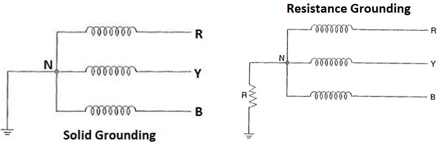
The solid grounding system involves solidly grounding a power system component through a grounding transformer. This is an easy installation and offers many safety improvements to an otherwise ungrounded system, but it offers no current-limiting capability because the grounding transformer alone does not have much resistance.
Thus, a more secure system is usually established by adding a neutral ground resistor to the grounding transformer to help limit ground fault currents’ magnitude. This arrangement is called resistive grounding. Choosing the ohm value of the resistor is a delicate step in implementing resistive grounding because the resistance must be high enough to prevent large fault currents from flowing in the system but must also be low enough so that it can limit thermal damage. Both of these arrangements are shown in Figure 1.
Figure 1: Solidly Grounded system and a Resistance Grounded system
2. Zig-Zag Vs. Wye-Delta Connections
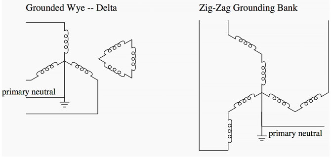
The geometry of the zig-zag connection allows it to limit the circulation of third harmonics. It also does not require a secondary delta-connected winding to operate, reducing the transformer’s cost and size. In comparison, a Wye-Delta connected grounding transformer requires either a secondary delta-connected winding or a construction design that uses the 4- or 5-leg core arrangement. In both cases, the system provides a return flux path for any load unbalances on the primary winding. Both of these arrangements are shown in Figure 2.
Figure 2. Wye-Delta and Zig-zag connected configurations of Grounding Transformers.
Most modern power systems use the two-winding wye-delta configuration for their grounding transformers because it has multiple advantages over the single-winding zig-zag configuration. Some of these advantages are that:
- Zig-zag transformers are harder to design
- Two-winding transformers are easier to replace and upgrade.
- The Two-winding wye-delta transformers can be used to implement secondary loading and metering, which requires less protective gear and insulation
- The wye-delta transformer configuration is a more familiar technology than Zig-zag, and most manufacturers provide such transformers. In contrast, fewer manufacturers make an effort to specialize in zig-zag technology.
- The Two-winding transformer can be used to provide auxiliary power from the secondary winding of the grounding transformer.
How to Properly Specify and Select a Grounding Transformer
The system needs must be incorporated into any decision about selecting a grounding transformer. The following key parameters should always be considered during the entire selection process:
1. Primary System Voltage
One of the most important considerations for selecting the grounding transformer is the system voltage to which it has to be connected. Another voltage consideration for selecting the grounding transformer is its ability to withstand lightning surges. This is specified as the transformer’s basic impulse level.
2. Rated kilo-volt amperes (kVA)
Grounding transformers only have a very specific short-time operation during ground faults. Therefore, they are smaller and cheaper than continuous-duty transformers of the same kVA rating.
3. Fault current and duration
This is the total fault current expected to flow through the system in case of a ground fault. Ultimately, this is the current that must be grounded through the transformer. Therefore, the transformer must withstand the current magnitude, ranging between 100 – 1000 Amps, for a specific period of time, without getting damaged from the current flow or the resulting heating effect.
4. Continuous neutral current
Grounding transformers are not sized based on kVA ratings but their current ratings. The continuous neutral current is the amount of current that must pass through the neutral circuit without tripping any protective gear or device.
5. Impedance
The Impedance value can be defined in terms of ohm resistance per phase or as a percentage. It should be chosen such that, in case of a single line-to-ground fault, the voltages of the unfaulted phases do not exceed the temporary overvoltage withstand capability of the transformer and the rest of the system equipment.
6. Primary winding connection
It is important to specify the transformer’s primary connection type, i.e., whether it is configured based on Wye or Zig-zag design.
7. Auxiliary Loading
Transformers of Wye and Zig-zag primary winding configurations have their size considerations when it comes to auxiliary loading. This must be considered when choosing the correct transformer and operating a chosen transformer properly.
8. Secondary connection
If the transformer has a secondary winding, then the connection type (Delta or Wye) and voltage ratings of this winding should also be specified.
Important Features and Options to Consider for Designing a Grounding Transformer
The above characteristics can help specify and select the correct grounding transformer for your system. However, a few additional concerns must be considered when designing the transformer. These include:
- Special paint should be applied on the transformer body as required.
- The location where the transformer will be installed and operated should be considered, e.g., whether it will be used outdoors or indoors. Additional measures must be taken to protect the transformer in outdoor applications.
- Consider the application and the unique characteristics of the transformer fluid options (silicone, mineral oil, and natural ester fluids) before choosing one option. Make appropriate design changes to facilitate the chosen option.
- Consider the connectivity type based on the site, e.g., whether a live front or a dead front design is required. The terminals can also be located in different places on the body, e.g., on the sidewall or under a cover, and they can be enclosed or exposed.
- Temperature rise is normally expected to be 65°C, but that can vary based on location, ventilation, and application. Thus, it should be adjusted within the design if necessary.
- Environmental concerns like site elevation should be considered, and proper protective mechanisms should be installed to help the transformer operate in every scenario.
- In the case of resistance grounding, ensure that the rated voltage of the neutral ground resistor equals the line-to-ground voltage of the grounding transformer. Also, ensure that its current rating and duration also match the ratings of the grounding transformer.