
Choosing the correct K rated Transformer for your Solar System
The world is increasingly installing solar systems to meet the everyday power demands of modern-day civilization. However, these systems produce electrical energy in the Direct Current form, which needs to be converted to the Alternating Current form before being supplied to consumers through transmission networks. This is done through inverters and other power electronic circuits, and the resultant AC power is stepped up through power transformers before being fed to the common grid and supplied to customers for consumption. However, introducing these AC electrical outputs causes some power quality issues in the rest of the grid.
One of these power quality issues is harmonics, which arise due to the non-linear nature of the solar inverter and other electronics in the solar panel assembly. Harmonics are the unwanted positive frequency multiples of the fundamental frequency of the output AC power of the solar inverter and electronics. These introduce noise to the system, which changes and distorts the wave shape of the AC power. Excess distortion can cause the current and voltage profiles of the solar output to deviate from the normal pure sinewave shape. This, in turn, affects the power profile and characteristics of the solar system as it is the product of these two profiles. Harmonics also cause certain phenomena in the system that adversely affect its performance, e.g., Resonance, heating, increased skin effect in coil devices, malfunctions of grid-side protection equipment, additional grid losses, production of zero sequence currents, etc., are all caused due to such harmonics.
The harmonics created by the solar power inverter are especially severe because inverters operate at much larger frequencies than the fundamental AC power frequency. It is not uncommon for inverters to create large fluctuations of up to the 40th harmonic distortions. The heating caused by such distortions can damage most transformers and other connected devices. Different harmonic distortion standards like the VDE-AR-N4105 and EREC G83 require the Total Harmonic Distortion (THD, ratio between total harmonic RMS and fundamental RMS) to be limited to 3 to 8 % current and voltage distortion for PV integration to a grid system at the Point of Common Coupling (PCC). However, more non-linear devices in the grid can push the THD percentage to higher values. In such cases, it is important to consider further remedial solutions like K-rated transformers.
K-rated Transformers for PV systems
Transformers are the most susceptible part of the system, and they can tolerate up to 5 % THD without being derated and up to 15 % with negligible derating. However, the THD introduced by the PV setup (up to 8%) and the main grid can cause the THD to increase even beyond 15% and cause the heating in the transformer coils to increase to an unacceptable degree. Filters are commonly used to prevent power harmonics from transferring to the transformer and the rest of the grid, but their design can become complicated for higher-order harmonics. In such cases, additional safety can be provided more economically by adaptation techniques rather than mitigation techniques. One such adaptation technique is using special class transformers called K-rated transformers with a higher tolerance to THD than standard power transformers.
The K-rating of a K-rated transformer describes its tolerance towards nonlinearity and system harmonics. It describes the total harmonic current the transformer’s coils can withstand without generating heat beyond the specified temperature threshold limit.
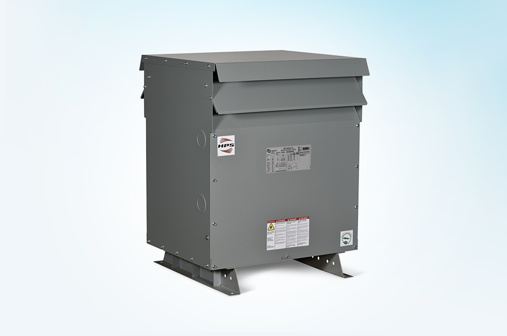
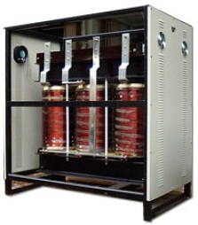
Figure. K-Rated Transformer:
The K-factor of a K-rated transformer can range between 1 to 50. Each K-factor represents a different level of THD tolerance, so transformers with subsequently higher K-factor values have more and more THD tolerance. This means that a transformer with a K-factor of 50 represents a transformer with the highest tolerance, while a transformer with a k-factor of 1 will have the lowest tolerance. Practically, the K-rating of a transformer shows how well the transformer can deliver the rated supply kVA output of the PV station to the connected grid with specified harmonic content.
Higher K-factor transformers have better harmonic performance, but the additional cost of such units means that they should not be chosen for PV systems arbitrarily. In fact, most PV systems can be connected to a power grid through one of the five K-rated transformers, i.e., K-1, K-4, K-9, K-13, K-20. These are the most widely used K-rated transformers for connecting a PV station to a power grid. Their commonly referenced ratings regarding THD tolerances are calculated using the ANSI/IEEE C57.11-1986 standard. These THD values are compared to the expected system THD values to find the appropriate transformer for making the required connection between the PV station and the power grid. Generally, the following IEEE rules are specifically followed while choosing the K-rated transformer:
K-Factor 1:
A transformer with a K-factor of 1 has the least tolerance against THD. Transformers that have this rating are only designed to handle eddy currents and losses caused due to the fundamental frequency of the sinewave AC power output of the PV station. It is not equipped to deal with the additional heating effects of harmonics and non-linear characteristics of the inverter circuit. These transformers are used when the harmonic current within the system gives a THD of 15% or less. These are also the cheapest option.
K-Factor 4:
A transformer with a K-factor rating of 4 has a small tolerance against THD. Transformers with this rating are designed to supply the rated KVA without overheating. These transformers have the ability to withstand four times the eddy current as the K-1 transformers. These transformers are used for systems with a harmonic current of up to 35% or less. The AC waveform consists of a 100% normal sinewave current waveform, with a harmonic breakdown: 16% of the 3rd harmonic current, 10% of the 5th harmonic current, 7% of the 7th harmonic current, 5.5% of the 9th harmonic current, and smaller percentages of up to the 25th harmonic.
K-Factor 9:
A transformer with a K-factor rating of 9 has 163% more tolerance against THD and harmonic currents than the K-4 transformers. They should be used to connect PV stations to grids for systems with up to 50% harmonic current.
K-Factor 13:
A transformer with a K-factor rating of 13 has 200% more tolerance against THD and harmonic currents than the K-4 transformers. They should be used for systems with up to 75% harmonic current.
K-Factor 20:
A transformer with a K-factor rating of 20 is designed to handle the PV connections that produce the most Harmonic currents, e.g., greater than 75%.

Key Takeaways
K-rated transformers are rated based on their ability to tolerate the non-linear behavior of the PV inverter and electronics system. Standard Transformers are listed within the K-1 category, while transformers with higher K-factor ratings are designed to reduce the heat produced by harmonics. They have special windings and large neutral conductors that effectively negate the skin effect and eddy current losses caused by the harmonics. A power quality meter can be used to check the K factor of a fully loaded system to find the required K-rated transformer for the PV system to grid coupling. The higher version is recommended if the calculated K-rating lies between two discrete available ratings.