
Harmonics in Transformers 101
AC power is the backbone of modern-day power systems. It is more economical and easier to manage than DC power. Ideally, the AC current and AC voltage waveforms are perfectly sinusoidal, predictable, and have a constant frequency and amplitude. However, the popularity of electronic devices (smartphones, laptops, etc.) in today’s world means that these waveforms are often distorted due to the nonlinearity of such devices. This deviation can be represented by harmonics and total harmonic distortion (THD).
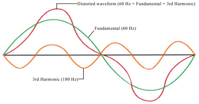
Harmonics are the unwanted positive frequency multiples of the fundamental frequency of the output AC power of the solar inverter and electronics. These introduce noise to the system, which changes and distorts the wave shape of the AC power. Thus, a pure AC waveform is free of harmonics and shows as a perfect sine wave. Harmonics also cause certain phenomena in the system that adversely affect its performance, e.g., Resonance, heating, increased skin effect in coil devices, malfunctions of grid-side protection equipment, additional grid losses, production of zero sequence currents, etc., are all caused due to such harmonics. The fundamental and harmonic components of a 60 Hz AC waveform are shown in figure 1.
It is important to quantify the harmonics’ effects so they can be removed. Here, the second term: total harmonic distortion (THD), is used. THD is a ratio of the total distortion RMS caused by all the harmonics and the fundamental wave RMS. The resulting value shows the percentage of a system waveform that contains harmonic distortion. Ideally, THD would be equal to zero, but that is never realized.
Figure 1: How a 3rd Harmonic Distorts the Fundamental Waveform. THD = 30%:
Why are current and voltage harmonics a problem?
Harmonics in the AC current and voltage profiles both present their challenges. Current harmonics are problematic because the distortions increase losses in the power system components on the utility and customer sides. Transformers are especially susceptible to current harmonics. The ANSI/IEEE C57.110-1986 standard lists the recommended practices for identifying the required capacity for a transformer in case of excess nonlinearity in the load current profiles. It states that standard transformers can tolerate up to 5 % THD without being derated and up to 15 % with negligible derating. However, if the THD goes beyond 15%, then the derating should be evaluated using IEEE recommendations. Transformers may need to get their operating capacity derated by as much as 50% for a 100% THD system. These recommendations are designed for standard transformers, not those already designed to feed non-sinusoidal loads like the K-rate Transformers. The special K-rated transformers are specifically tested and rated by MPS.
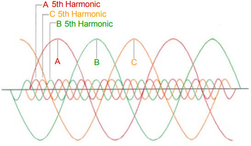
Harmonics can also distort the waveforms of the AC voltage profiles. These harmonics are called voltage harmonics. Such distortions also have severe repercussions as they affect all equipment attached to the power system, be they sensitive electronic devices or capacitor banks and electric motors. They can produce negative sequence harmonics ( 5th, 11th, 17th, etc.) that have an opposite sequence to the fundamental voltage sequence; If the fundamental sequence is ABC, then these harmonics produce a negative sequence of ACB, as shown in figure 2. These negative sequences produce a negative magnetic field, which rotates in the opposite direction to the magnetic field of the fundamental voltages. The resultant oscillation of the fields (due to two opposite fields) causes overheating and mechanical oscillation that can damage the motor-load system.
Figure 2: How the negative sequence 5th harmonic influences a balanced 3-Phase voltage system:
Single-Phase and Three-Phase Load Harmonics
Electronic ballasts, personal computers, and other single-phase non-linear loads generate odd harmonics (3rd, 5th, 7th, 9th, etc.) in the system. The “triplen” harmonics, which are made up of the odd multiples of 3rd harmonics (3rd, 9th, 15th, 21st, etc.), are especially troublesome because they flow in all three phases (ABC) and are completely in phase with one another. They, therefore, add on the neutral conductor of a three-phase 4-wire system instead of canceling, which causes the neutral to become overloaded if it is not sized to handle it. Additionally, this neutral current is passed onto the delta winding of a delta-wye transformer, where the current circulates within the windings. This results in transformer heating and producing power losses.
How to check for harmonic currents?
Harmonic problems arise because of non-linear elements in the system. There are two parameters to consider in such cases. The first is to find the number of non-linear elements in the system. If more than 20% of the system is non-linear, the harmonic problem cannot be neglected. The second consideration must be made regarding the type of load on the system, e.g., electronic ballasts have a current THD between 6% and 100%. Here, it should be ensured that only ballasts with 20% THD or less are added to the system; otherwise, considerable harmonic current will flow in the system.
Another way to verify the presence of harmonic currents is to measure the neutral current in the 3-phase 4-wire system. If the neutral current exceeds the expected value that would arise in case of phase imbalance, then there is a strong possibility of the system being affected by triplen harmonics.
Other parameters like transformer temperature, crest factor, and voltage distortion can also be used to verify the presence of harmonic currents indirectly.
What is the Crest factor?
The crest factor of an AC waveform is the ratio of its peak value and its RMS value. The crest factor for a perfect sine wave is 1.414. If the crest factor for a system voltage or current waveform is different from 1.414, then the waveform is not perfectly sinusoidal, and there is distortion and harmonics in the system.
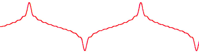
Distorted current waveforms typically have higher crest factors (2.2 to 3), as shown in figure 3 , while the crest factor of distorted voltage is lower than 1.414. The distorted voltage waveforms are called “flat top” waveforms due to their shape.
Figure 3. A current waveform with a high crest factor:
The CBEMA (Computer and Business Equipment Manufacturers Association) recommends a method for derating a transformer depending on the crest factor of the current waveform on the secondary side of a transformer.
In this method, a parameter known as the transformer harmonic-derating factor (THDF) is used to determine the capacity decline of the transformer due to system nonlinearity. The THDF is the ratio of the crest factor of the pure sine wave (1.414) to the crest factor of the transformer current. The capacity loss is then measured by multiplying the nominal kVA rating of the transformer by the THDF. The loss is then used for derating the transformer’s kVA capacity while delivering a non-linear current to the grid. Two precautions should be considered when applying this method. One, this method should only ever be applied for non-linear single-phase loads, and two, the crest factor measurements should be taken from the secondary side current of the transformer. A more complete method is defined by the ANSI/IEEE C57.110-1986.
Key Takeaways
Harmonics only become a problem when a system design cannot deal with them satisfactorily. For example, neutral currents can be an issue only if the neutral wire is not properly sized, and current harmonics are a problem if the transformer is not derated properly to account for the system’s nonlinearity. Voltage distortions may also be tolerated if the THD is less than 8% at the point of utilization.
Minimizing harmonics improves the system performance, reduces power system losses, and improves the system power factor. Therefore, it is important to identify and reduce harmonics as much as possible, especially when the non-linear load on the system is increased.