
How to Test a Transformer
There are various power transformer tests to ensure they function properly and safely while adhering to certain performance standards. These tests include Factory Acceptance, Commissioning, Routine Maintenance, and Diagnostic tests, performed at different stages of the transformer’s lifecycle.
Three primary tests, namely the Open-Circuit, Short-Circuit, and Winding Resistance Measurement tests, are employed to assess the transformer’s no-load, full-load, and I2R (copper) losses, respectively. These tests are crucial to understanding and predicting transformer behavior under different operating conditions.
Open-Circuit Test
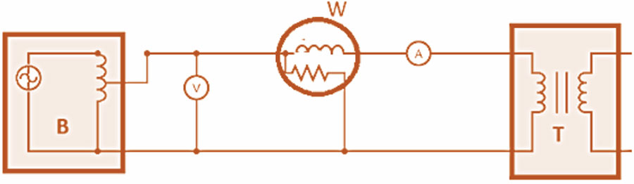
The Open-Circuit test measures the no-load losses of a transformer. It is performed by energizing a transformer with its secondary winding kept open. Thus, the transformer consumes all the energizing current as it does not supply any load. To better understand how to conduct an open-circuit test, we’ve created a diagram detailing the arrangement of connections for an open-circuit test in Figure 1. Listed below are the required components for an Open-Circuit test:
- A: Ammeter
- B: Autotransformer
- T: Transformer being tested
- V: Voltmeter
- W: Wattmeter
Figure 1 : Open-Circuit Test
Autotransformers are single-winding transformers whose winding can be tapped at different points to generate varied and well-regulated voltages. An autotransformer is connected to an AC voltage source for the Open-Circuit test, as shown in Figure 1. The winding is tapped at a required point to obtain the output voltage, monitored with a voltmeter. Listed below are three steps on how to conduct the Open-Circuit test on a transformer:
- The secondary of the transformer is kept open-circuited.
- The voltage applied to the primary side is gradually raised until it reaches the transformer’s rated voltage level (as indicated on the transformer’s label). The voltmeter is used to monitor this phase of the test.
- Once the rated voltage is attained, readings from all three instruments—wattmeter, voltmeter, and ammeter—are noted. The values recorded from these meters can help determine certain parameters:
- The ammeter reading gives the No-Load Current value because there is no current flow in the secondary winding due to the open circuit.
- The voltmeter reading measures the Induced Voltage on the open-circuited secondary winding, which is equal to the applied voltage.
- The wattmeter measures the Core and Copper losses of the transformer.
The recorded no-load current is considerably lower than the transformer’s rated full-load current, resulting in negligible copper losses. Therefore, the open-circuit test is mainly used to measure the core losses within the transformer to indicate any issues within its magnetic core.
Short-Circuit Test
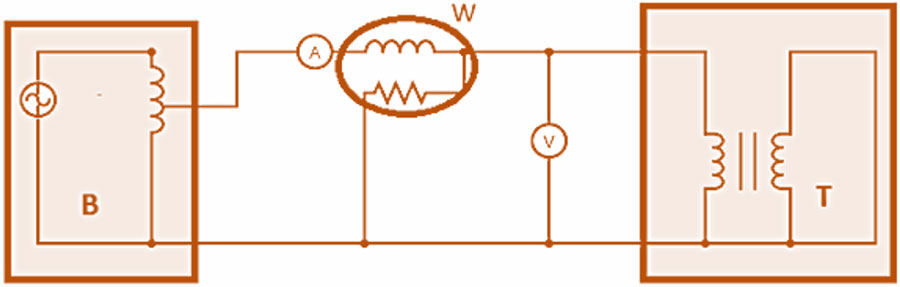
The Short-Circuit test measures the full-load losses of a transformer. It is performed by energizing a transformer with its secondary winding shorted. Thus, the secondary winding resistance drops to zero, and maximum current flows in the secondary winding. The arrangement of connections for conducting a short-circuit test on a transformer is illustrated in Figure 2. The required components for a Short-Circuit test include:
- A: Ammeter
- B: Autotransformer
- T: Transformer being tested
- V: Voltmeter
- W: Wattmeter
Figure 2: Short-Circuit Test
The following steps must be performed to conduct the Short-Circuit test on a transformer:
- The secondary of the transformer is short-circuited.
- An autotransformer is used to apply a low voltage, typically ranging from 7-10% of the transformer’s rated voltage, to the primary side of the transformer. The autotransformer winding allows for tapping at various positions, resulting in a range of voltages.
- The applied voltage is increased slowly until the wattmeter and ammeter provide a reading equivalent to the rated current of the transformer.
- The readings on the wattmeter, voltmeter, and ammeter are noted. The recorded values can help determine certain parameters:
- The ammeter reading provides the Full Load Current value because the short-circuit current flows in the secondary winding due to the short circuit.
- The wattmeter measures the Core and Copper losses of the transformer.
The measured voltage is very small compared to the transformer’s rated voltage and produces negligible core loss. Therefore, the short-circuit test is mainly used to measure the transformer’s maximum copper losses (I2R).
Resistance Measurement
The winding resistance measurement test measures the winding resistance of the transformer so that system operators can calculate I2R losses in the transformer and check for signs of damage in its windings. The transformer winding resistance can be measured through a simple circuit, as shown in Figure 3. The required components include:
- A: Ammeter
- DC: DC voltage source
- R: An external resistance of specified value
- T: Transformer that has an effective inductance and resistance value
- V: Voltmeter
Figure 3: Resistance measurement
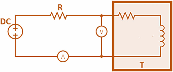
A DC voltage is applied to the circuit to initiate a current flow through the transformer winding. The voltage drop across the winding and the test current are measured to calculate the winding resistance.
Understanding Transformer Parameters and Key Terminologies.
Before measuring transformer parameters like core losses, copper losses, and winding resistances, you must first understand what you need to measure and become familiar with key terminologies like primary current, secondary voltage, leakage inductance, and winding capacitance.
1. Transformer Parameters
a. Core Losses
The amount of energy that is lost as a result of core excitation of a transformer unit.
b. Copper Losses
The amount of energy that is lost as a result of current flow in transformer windings.
c. Winding Resistance
The amount of resistance offered to current flow by the transformer windings.
2. Key Terminology
a. Primary current
The primary current of a transformer is the direct output from its primary winding that is used to check transformer performance. An increase in primary current
implies that the secondary winding transfers more power, indicating that the transformer is suitable. In contrast, decreasing primary current indicates a poorly configured or faulty impedance-matching circuit.
b. Secondary voltage
The secondary voltage of a transformer is the output from its secondary winding that is used to check the condition of the secondary circuit insulation and wiring. A high value can indicate the presence of arcing contaminations and short circuits due to shorts and blockages. However, a low value indicates that the impedance matching circuit is poorly configured, among other things.
c. Leakage inductance
The leakage inductance of a transformer is the amount of current that can flow in its winding when no external voltage is applied. Transformers with high leakage
inductance values have a short operation at high frequencies. Such transformers are primarily used to provide faster firing pulses in short-circuiting applications, such as capacitive effects and controlled detonation devices (CDDs).
d. Winding capacitance
The winding capacitance of a transformer refers to the quantity of voltage and current required for charging and discharging the secondary winding through the
circuit. The additional voltage and current requirement for sustaining the winding depends upon the presence of notable resistance in the circuit. A high capacitance value can lead to the transformer operating at increased frequencies and reaching saturation at lower voltage levels.
The open-circuit, short-circuit, and winding measurement tests are vital to understanding how much power can be transferred through a power transformer under different operating conditions to ensure its safe and reliable functioning. At Meta Power Solutions, engineers, proficient technicians, and specialized testing laboratories execute these tests with the essential equipment and expertise. The outcomes of these evaluations can guide decision-making regarding transformer repair, maintenance , and replacement work.