
Introduction to Transformer Losses
Transformers are essential electric devices because they play a vital role in performing different functions in power systems. However, they are not perfect, and they exhibit certain types of power losses that must be considered within the expected outcomes of their operation. These power losses cause the transformer device to lose a portion of its intake power in the form of heat. This heat causes two issues:
- The heat reduces the output power of the transformer, which becomes less than the input power. And,
- The heat requires additional protection equipment that can help the transformer cool down.
Power system designers and operators must become familiar with the different transformer losses to prevent them from hindering power system operations by taking loss minimization steps. There are two main losses within the operation of a transformer. These are the Iron losses produced in the transformer core and the Copper losses produced due to the current flow in the transformer coils. These two losses are described in detail below.
Figure 1. Two types of Losses in Transformer:
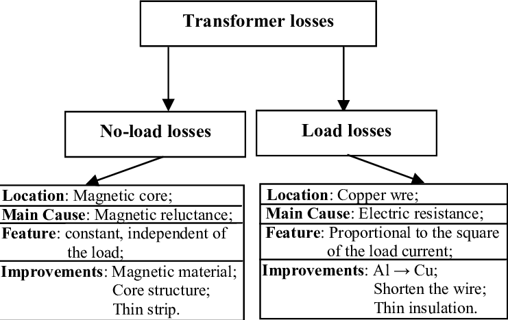
1. Iron Losses
A transformer can transform the current and voltage amplitudes by using the magnetic linkage between two different coils with different turns. The linkage is done through a magnetic core to link more flux between the two coils on the transformer’s core. The design of the core and the way flux flows through it can cause certain losses, irrespective of the loading on the secondary coil of the transformer. These losses are called iron losses. As these losses are formed by the flow of magnetizing current and not the load current, these losses are also called no-load losses. Iron losses are further categorized into two classifications: Eddy current losses and Hysteresis losses.
A. Eddy Current Losses
The transformer core is made of laminations of magnetic materials, like high-grade silicon steel laminations, that are secured together.
When the transformer is energized, AC current starts to flow through the primary winding, and a subsequent output current is derived from the secondary windings due to the linkage between the two windings. A portion of the primary current, known as magnetizing current, is used to form this linkage, irrespective of the load on the secondary winding. However, this current has an alternating magnetic field around it that cuts through the magnetic material laminations and induces small voltage (EMF) in them. The core laminations, therefore, start to conduct electrical currents in closed loops. This current, known as eddy current, flows through the resistances offered by the core body and generates heat. This excess heat reduces transformer efficiency and introduces power losses if it is not removed through specialized protective gear.
Eddy current losses can be reduced by decreasing the thickness of the laminated sheets. This helps reduce the resistive path offered to the eddy current flow. A second correction method is to apply insulating varnish between adjacent sheets to force the eddy current to remain within smaller paths of the individual laminations.
The material of the laminations also plays an important role in restricting the eddy current losses. For example, 0.014′′ thick Nickel-iron and silicon-iron alloy sheets can be used instead of thicker pure iron sheets to get easier magnetization and improved age resistance for the core.
B. Hysteresis Losses
Hysteresis is a Greek word that means “to lag”. This refers to the lag between the magnetic force (the leading property) and the magnetic flux (the lagging property).
When the transformer is energized with an AC supply, the transformer core links two coils magnetically and the magnetic core material molecules, known as magnetic domains, are arranged and aligned throughout the core body. The direction of the alignment changes with the polarity and availability of the AC waveform; for example, a 50Hz supply would change the orientation a hundred times in either direction. Ideally, the molecules would readily change their alignment each time the core is energized and de-energized. However, the molecules give a small opposition against every attempt, and this resistance causes friction that produces heat in the body of the core. The wasted energy in the form of heat causes power losses in the system. The Hysteresis losses in the transformer core cause the majority of iron losses.
Hysteresis losses can be lowered by choosing the appropriate core material size and type. For example, the silicon steel lamination sheets have small hysteresis loss.
Both iron losses, eddy current, and hysteresis losses exist even if there is no load on the transformer. They are measured by energizing a transformer in a no-load state and conducting the open circuit test to measure the input power. As no power is being delivered to a load on the secondary winding, the power must be consumed by these losses.
2. Copper Losses
The other major type of transformer loss is called Copper loss, which is the energy lost from the transformer when it delivers current to a load connected to its secondary winding. This energy is lost in the form of heat due to the flow of the load current through the winding resistances. For modern-day transformers, the winding resistance is relatively low. However, the power lost due to the resistance is directly proportional to the square of the current flowing through it. Larger loads require more current, exponentially increasing the copper loss in each winding. The total copper loss in a transformer can be calculated as follows:
P Cu = I p2 R p + I s2 R s
Where R p and R s are the resistances and I p and I s are the currents of the primary and the secondary winding, respectively. This is why copper losses are also known as I 2R losses. Copper losses can be calculated using the short-circuit test.
Copper losses depend on the current requirements of the load on the secondary winding and the resistances of both windings. The current aspect is determined by the load and cannot be changed to control such losses. This means copper losses can only be controlled by reducing the winding resistances. This can be achieved by using more conductive material to make the windings, preferably copper, because it is the best conductor in terms of cost, size, weight, and resistance.
Transformer Efficiency
The efficiency of a transformer is the ratio between its output and input power. Ideally, a transformer would have an efficiency of 100%. However, iron and copper losses cause the output power to be lower than the input power. Transformer efficiency is a measure of the degree of loss in a transformer device. It is measured through the following formula:
η = P OUT / PIN
Where η is transformer efficiency (in %) , P OUT is the output power (in W) , and P IN is the input of the transformer unit (in W).
Example:
Calculate the transformer efficiency if it is supplied with 2000 W and outputs 1980 W.
η = POUT / PIN
η = 1960 W / 2000 W
η = 98 %
Most power transformers have an efficiency between 97 to 99 %. This means that the output
power is always less than the input power due to the different losses in the transformer device.