
Power Transformer Components
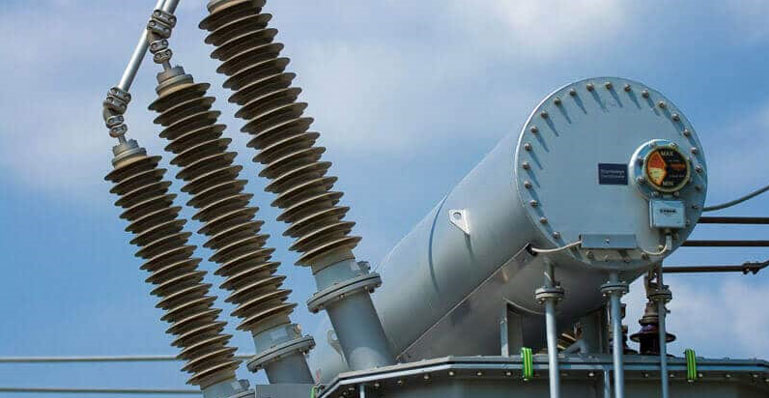
A power transformer alters an electrical power signal’s voltage and current characteristics to facilitate its flow in circuits with different power considerations and ratings. Like all other transformers, power transformers are considered static electrical machines due to the absence of moving parts. Tap-changers and protective valves do move, but not during the stable operating periods of the transformer. Power transformers can be used as step-down or step-up transformers to increase and decrease the voltage and current levels of the electrical signals as required. This voltage and current level changing process of a transformer only applies to AC supplies and works on the principles of mutual inductance. The power and frequency of the electrical signal on either side of the power transformer remain the same, which means that the same power is transferred between circuits that work on different voltage and current levels.
Power transformers play a crucial role in high-voltage electrical transmission grids by adjusting voltage levels to meet the varying needs of electric power users while maintaining constant power output (neglecting the losses). These electrical machines are typically constructed using copper, steel, paper, and insulating oil, which are transformed into various components, including windings, tap changing systems, cores, tanks, and bushings. These components are then assembled to form a power transformer. The basic designs established almost a century ago for power transformers continue to be widely used and adapted for various special applications worldwide.
Key Components of a Power Transformer
A power transformer consists of various unique components, each contributing differently to the overall performance of the transformer. The core, windings, tap changer, insulating materials, transformer oil, conservator, breather, Buchholz Relay, cooling tubes, and explosion vent are among the primary components.
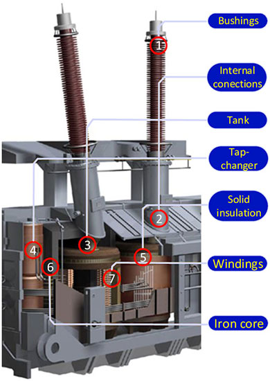
Most transformers have a core, windings, insulating materials, and transformer oil, while those rated above 50 KVA come with additional components. In this article, we will discuss the primary components of power transformers.
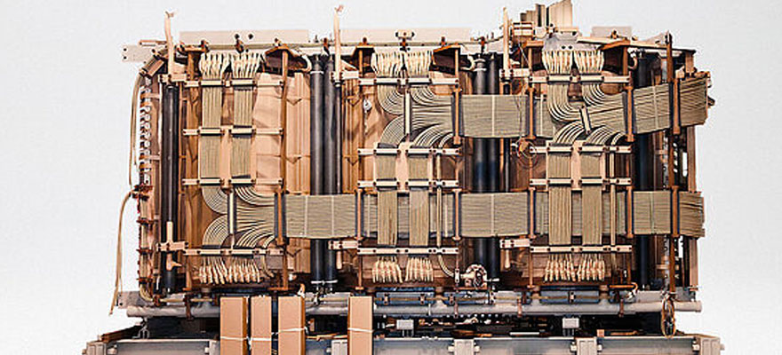
Windings
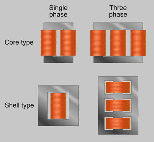
The main component of a power transformer is its windings, which can be compared to the heart of the human body. These windings are typically handmade using copper or, in some cases, aluminum coils insulated with several layers of paper between the turns. Over time, two main winding designs and technologies have emerged, with various variations: the core and shell types. Although both designs share the same electromagnetic basis, their mechanical construction differs. In the core type design, the winding surrounds the magnetic core legs, while in the shell type, the core encloses (and runs through) the windings. Each manufacturer has a unique experience with these winding technologies, neither of which can be fully automated.
The manufacturing process of windings involves a considerable amount of manual labor and requires extensive experience and adherence to strict quality standards. This is due to the fact that winding conductors are covered with a type of insulation, such as varnish or insulating paper, which has limited thermal and mechanical stability. However, this insulation protects against short-term overheating, high overcurrents, high overvoltages, and high mechanical stresses to prevent any degradation of the durability of the insulation paper. It’s essential to consider that the winding insulation cannot be repaired or replaced easily during the transformer’s service life, and rewinding should only be done in a specialized workshop.
Core
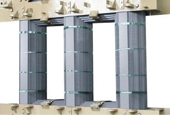
The core is a crucial transformer component and typically the heaviest one. It is manufactured from steel with high magnetic permeability and low magnetic resistance to the magnetic flux. To minimize losses and magnetizing current, the core is produced from thin steel sheets with a thickness of only a few tenths of a millimeter. The usual method for creating a core involves stacking the sheets, which are cut to the required size, onto automated machines, and then manually assembling them to form a core. For single-phase small distribution transformers, wound cores offer greater efficiency and productivity.
The core comprises two main parts – legs (vertical) and yokes (horizontal). Typically, the legs are situated in the same plane, although in the case of three-phase transformers, the legs can be arranged in a triangular-spaced configuration, known as a hexaformer. Small-sized distribution transformers are sometimes manufactured using hexaformer core design, but their market share is quite limited. Even though hexaformers have the advantage of producing lower losses, transformers with ‘traditional’ core are still more efficient and productive.
Insulating materials
Power transformers typically use three main insulating materials: mineral oil, paper, and pressboard in various forms. The mineral-insulating oil contained within the tank can provide valuable insights into the transformer’s condition and detect potential faults. The paper material is used to insulate the winding turns, while the pressboard is utilized to reinforce electrical insulation and provide dielectric spacing at specific locations, such as in the primary duct between the windings.
Organic insulating materials like paper, pressboard, and mineral oil are subject to aging, limiting a transformer’s service life. Unlike other transformer components, the insulation cannot be easily repaired or replaced; thus, its lifetime defines the overall lifetime of the transformer.
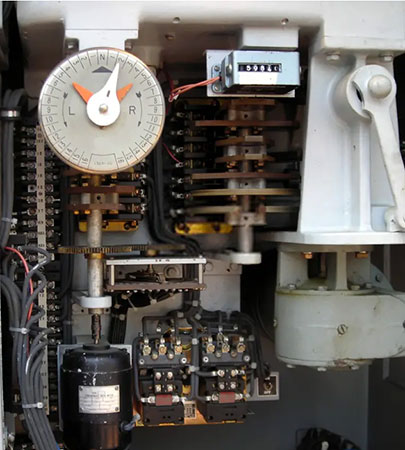
Tap Changer
Most transformers are equipped with additional turns in their high voltage (HV) windings, some of which are connected to a device known as the “Tap Changer.” This device permits a specific range of voltage variation throughout the transformer’s service life. Both the windings and the tap changer have movable contacts within their electrical circuits. Two main types of tap changers are the De-energized Tap Changer (DETC), which is mechanically simple and changes the voltage while the transformer is not under load, and the On-Load Tap Changer (OLTC), which is a more complex type that operates while the transformer is supplying the load.
It is worth noting that tap changers, particularly the On-Load Tap Changers (OLTCs), are responsible for an increasing rate of transformer failures, largely due to the wear and tear of movable contacts over time.
Bushings
The bushings are the critical components that connect the windings to the power system through the grounded tank. Designing high-voltage bushings can be a technically intricate process; if they fail, a transformer explosion may occur quite rapidly. This is due to the significant voltage gradient between the HV bushing’s central part at full potential and the grounded tank, which is just a few centimeters away. Additionally, the insulating oil located just beneath the HV bushing is highly flammable, and any sparking within the bushing can release a significant amount of energy, causing the tank to open slightly and ignite the oil, resulting in an explosion. As a result, HV bushings are constructed to withstand extremely high voltages within a small space filled with oil and paper insulation between the tank and bushing.

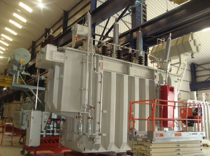
Tank
The transformer tank houses the oil, providing physical support and protection to the transformer’s various components, in addition to grounding the magnetic circuit and various metal parts.
Tank bodies are produced by molding rolled steel plates into containers and installing lifting hooks and cooling tubes. In some cases, aluminum sheets may be used instead of steel plates to reduce the transformer’s weight and prevent stray losses.
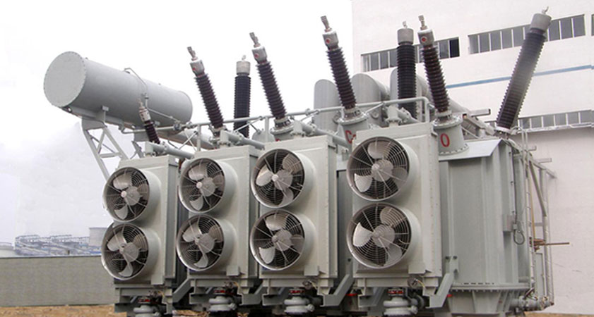
Cooling system
Cooling in a large power transformer is achieved through the forced circulation of either oil and water or air, facilitated by pumps and fans. The cooling method is classified based on the internal and external cooling medium type and the circulation they undergo. For instance, the code ONAN represents a transformer with mineral oil as the internal cooling medium and air as the external medium, and the circulation in both cases is natural. Usually, internal cooling involves forcing mineral oil, denoted as “O,” through the radiators and directing it towards the “D” windings, while external cooling employs either “A” air or “W” water. External circulation is indicated as “N” for natural air convection and “F” for forced circulation. A single transformer can have multiple cooling types, and depending on the temperature and power to which it is subjected, the fans and/or pumps can be activated or deactivated.
Optional Components
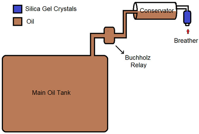
Air Breather
An air breather is installed on the oil conservator of a transformer to accommodate the oil volume changes due to temperature fluctuations during normal operation. The air breather includes silica gel, which absorbs moisture from the air. Silica gel is blue upon delivery and turns pink upon moisture absorption. The silica gel can be reused by heating it to 120 degrees Celsius until it returns to its original blue color.
Oil Conservator
The primary function of the oil conservator tank is to provide sufficient space for the transformer oil to expand and contract due to ambient temperature changes in the main transformer tank for transformer oil.
This drum-shaped structure is installed on top of the transformer tank. It includes a Buchholz relay mounted on the pipe connecting it to the tank and a level indicator to display the oil level in the conservator tank.
Buchholz Relay
Oil-immersed transformers rated above 500kVA require Buchholz relays as a crucial component. These relays work alongside the conservator to detect internal faults such as oil leakages, gas formations, and quick oil flow. Dry contacts are provided to signal the alarms when these faults occur.
Explosion Vent
During an emergency, the transformer’s explosion vent serves as an outlet for releasing oil and air gases. This component generally includes a metallic pipe with a diaphragm on one end and is positioned just above the conservator tank.
In the event of oil leakage, excessive pressure can build up inside the tank, leading to hazardous situations. In such cases, the diaphragm ruptures at low pressure, allowing the forces inside the transformer to escape into the atmosphere.
Drain Valve
Typically located at the bottom of the transformer tank, drain valves are employed for oil replacement purposes. The oil-filled transformer can be conveniently refilled by opening this valve, similar to a faucet.
Oil Temperature/Pressure gauges
These gauges are employed to monitor the transformer’s internal characteristics, particularly its windings. These instruments aid operators determine the temperature and pressure levels within the transformer’s oil and windings. Furthermore, they serve as an alarm when levels reach potentially dangerous thresholds that may harm the transformer’s windings.
Conclusion
Power transformers are integral parts of high voltage grids, responsible for minimizing energy losses during the transmission of electrical energy across wide areas. Power transformers include several key components such as the core, windings, insulation, tap changers, cooling systems, conservator tanks, Buchholz relays, explosion vents, drain valves, and gauges. These components work together to ensure the safe and efficient operation of the power transformer.