
Transformer Electrostatic Shielding
Overview
Harmonics and transient noise were originally present in only the electronics industry. As the penetration of electronic devices increased in every household, these problems also began to emerge in the power sector. The wide network of the power system meant that a significant load could be instantaneously disconnected from the grid. This causes large voltage swings and power surges in the network. Before switched mode power supplies became the most popular means of supplying electronic loads, step-down transformers were used to reduce the line voltage to a level that could be used to supply power to electronic devices. At that time, electrostatic shields were used to protect the load equipment from transients and power surges, and the technology is still in use today. Electrostatic shielding capabilities are commonly specified on the datasheets/nameplates of different transformers, especially isolation transformers. These shields introduce a capacitive decoupling effect between the primary and secondary windings, which does not allow transients to pass on to the secondary windings. The inductive coupling of the windings is not affected through shielding, so the transformer can continue to deliver power to connected loads.
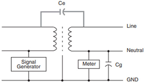
Figure 1. Shielding when the secondary is not connected to equipment ground:
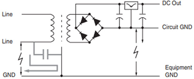
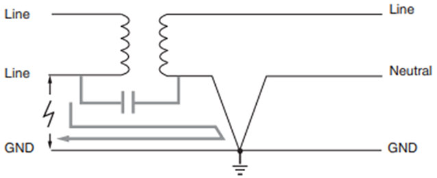
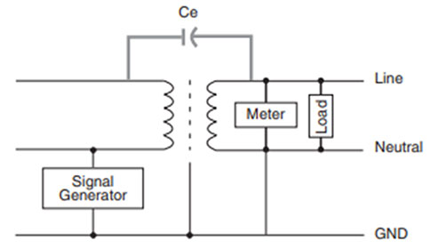
Figure 2. Grounded Secondary to Prevent Common-Mode Noise:
Electrostatic shielding has applications in the electronic and power industry, but there is a distinct difference in how it is applied to the transformers in both cases. In electronics, electrostatic shielding is used when the secondary connected load circuit and the primary power supply have different grounds. Thus, the shield is used to prevent the formation of differential signals between these grounds by capacitively shunting away unwanted transients from the primary line of the transformer. This is shown in Figure 1.
However, in power systems, the transformer primary and secondary are both connected to the same ground, and the ground of the secondary-connected loads is also connected to it, as shown in Figure 2. The primary and secondary sides of the transformer are both solidly connected to ensure that there is no floating secondary voltage that could harm the secondary-connected loads. The Neutral grounding also protects the secondary loads from common-mode transients, which are returned to the primary source without needing an electrostatic shield.
It is common to misunderstand how these two applications vary. This confusion is expounded by the transformer manufacturing industry, which continues to foster a large market for distribution transformers and selling them with the added value of electrostatic shielding. However, test data reveals that shielding plays little role in load protection; rather, the data shows that the shielding itself might cause transients in loads in some cases.
Typical Applications
Electrostatically shielded transformers protect sensitive electric load equipment from high-frequency transients and power surges caused by thunderstorms, loss of load swings, etc. Lighting loads, motors, and SCR switches are common sources of most high-frequency transients in the power system. A single turn of aluminum foil can be used between a transformer’s primary and secondary windings to get electrostatic shielding with a common-mode noise attenuation between 30 dB to 70 dB.
Shielded isolation transformers are typically used to:
- Suppress transients and noise to protect sensitive load equipment.
- Suppress transients and noise at the origin to prevent them from back feeding from the source.
- Change the voltage level from primary to secondary.
- Isolate and protect one circuit from another.
Testing
In the past, attempts were made to design a universal testing standard for transformer shielding. However, these attempts failed, and no universal standard exists at this time. Thus, each manufacturer decides its criteria for performing transformer shielding tests. The lack of a standardized procedure has created uncertainty in the industry, as different manufacturers base their claims on their criteria, which cannot be refuted. Manufacturers also do not pay attention to factors like high-frequency performance and resonant points because such considerations would put them at a disadvantage over their competitors. The manufacturer often designs their system based on a single attenuation value over a wide frequency range.
Figures 3, 4, and 5 show common shielding tests. Some characteristics are common in each test:
- Tests are performed on de-energized transformers.
- The tests do not use real surges and impulses, as they only use sine wave signal sources.
- So far, no comparisons have been made between non-shielded and shielded transformers.
Insertion Loss Tests
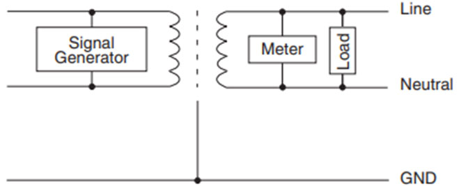
The insertion loss test involves the transverse mode testing of the shield, which is done by applying a transient signal on the line-to-line input terminals of the transformer and judging the shield performance. The secondary-connected load can be varied to attain attenuation values between the -30 dB to -60 dB range. Some manufacturers enhance their high-frequency results by adding capacitance to the load. The frequency of transients is a critical factor in determining the attenuation in this test. Thus, attenuation values are better indicators than the frequency band of the test signal.
Figure 3: Insertion Loss Test:
Common-Mode Tests
The common-mode test of the shield is performed by applying a transient signal on the transformer’s line-to-ground terminals. Common-mode testing is similar to filter testing, but unlike filter tests, there are no standards to specify the load impedance in the case of the Common-mode tests. The signal attenuation observed in this test is determined by the relationship between two capacitances. These capacitances are the effective coupling capacitance (Ce) between the two windings and the ground capacitance (Cg) between the neutral of the second winding and the ground. Because the type and impedance value of the load is not standardized, Cg can be varied to obtain the required attenuation value. Different manufacturers have made performance claims in the range of -50 dB to -152 dB. The setup of the test is shown in Figure 4.
Figure 4: Common-Mode (Line-to-Ground) Test:
Common-Mode/Transverse-Mode Tests
In actual applications, the transformer secondary neutral is grounded. Therefore, the Common-mode test cannot be performed as the Cg parameter is zero. Some manufacturers, therefore, modify the test and call it the “common-mode/ transverse-mode” test. The modified setup is shown in Figure 5. Standards do not specify the load type and impedance, so manufacturers choose loading values at their discretion. They choose values that give them a specification advantage. Typical values of attenuation range from -85 dB to -120 dB, and the frequency is not specified.
Figure 5: Common-Mode/Transverse-Mode Test:
Conclusion
The transformer installation follows the National Electrical Code (NEC), which defines the secondary side of the transformer as a separately derived source. According to the NEC standards, only the installations without a neutral can be left ungrounded. About 95% of transformer installations follow the NEC standards. Therefore, most transformers are installed with their secondary winding/load side neutral grounded. Electrostatic shielding can be beneficial in electronic systems where the load neutral is not in common with the primary side ground. However, they have little to no impact in systems where the transformer’s primary and secondary sides share the same ground – e.g., distribution transformers. On the other hand, most test results on distribution transformers indicate that including an electrostatic shield could even induce transients in the load device under certain conditions.
The specification for transformers should be determined based on the expected applications and relevant test data. A few recommended steps should be followed to ensure the proper transformer specifications.
- Proper specification practices for the transformer’s electrostatic shielding ability to ensure that it is properly used for required applications. It should be noted that the shielding property of such transformers does not always boost the transformer’s overall performance.
- Manufacturers who ship the electrostatic shielding as a standard practice for value addition should be avoided in general. The shield does not boost performance in all scenarios; in fact, it can actively harm the performance by producing harmonics and degrading the power quality under certain conditions.
- Shields should be considered only in those applications where noise attenuation is required. They are not universal protection devices.
- The most significant factor in determining the power quality of distribution systems is shown to be grounding. A proper ground should be made to prevent common-mode noise from harming load devices, even without electrostatic shielding.
- Isolation transformers should be placed as close as possible to the sensitive electronic equipment.