
Understanding Transformer Technology
Transformers are at the heart of modern electrical infrastructure, enabling efficient voltage conversion and safe power transmission across residential, commercial, and industrial systems. Whether you're a student, technician, or procurement specialist, understanding how transformers work is essential to selecting and maintaining the right equipment.

Everything We Do Is At A High Standard
Request A Custom Quote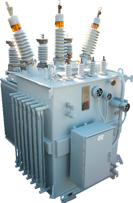
How Does a Transformer Work?
At its core, a transformer operates on the electromagnetic induction principle, first discovered by Michael Faraday. The basic idea is simple but powerful: when an alternating current flows through a coil (the primary winding), it generates a changing magnetic field. This magnetic field, when passed through a magnetic core, induces a voltage in another coil (the secondary winding).
This process allows the transformer to increase (step-up) or decrease (step-down) voltage levels without changing the frequency of the electrical signal.
Types of Transformers
based on Construction and Design
The electrical transformer is an engineering marvel and an extraordinarily vital component in our power system and everyday lives. It is a static device with no moving parts and two electrically isolated coils (primary and secondary) connected to a different electric circuit. The transformer transfers electric power between these isolated electric circuits through Michael Faraday's electromagnetic induction mechanisms. It uses Faradays Law of Electromagnetic Induction to change the voltage of an AC electric power signal without changing its frequency.
This article describes how transformers are classified based on their voltage transformation characteristics, winding construction, core design, and purpose. We have also shown how the different types of transformers follow the same working principle.
Classification of Transformers
Based on Voltage Transformation Characteristics
- Step-Up Transformer
- Step-Down Transformer
- Isolation Transformer
Based on the Number of Phases
- Single-Phase Transformer
- Three-Phase transformer
Based on Core
MATERIAL
- Iron Core Transformers
- Ferrite Core Transformer
- Air-Core transformer
DESIGN
- Solenoidal Core Transformer
- Toroidal Core Transformer
Based on Application
- Power Transformers
- Instrument Transformers
- Distribution Transformer
- Current Transformer
Based on Cooling Medium
- Dry Type Transformer
- Oil Type Transformer
Based on Voltage Transformation Characteristics
This classification is based on how the transformer changes the voltage level of an AC signal at its primary coil to give a resultant, deterministic signal at the secondary coil. A transformer can be categorized into three types based on its action on input voltage: Step-Up, Step-Down, and Isolation Transformer.
Request A Quote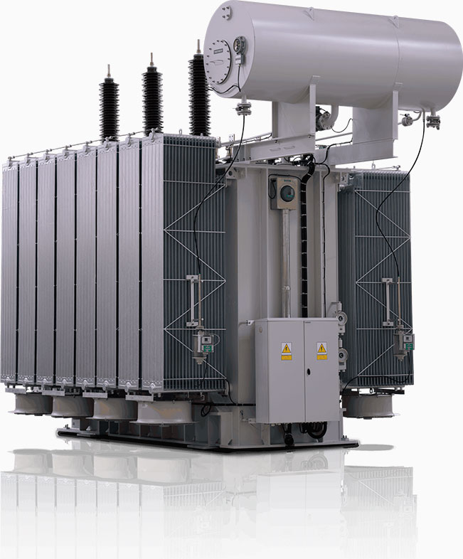
Step-Up Transformer
A step-up transformer increases the voltage level of an incoming primary signal. The higher output voltage is obtained through the winding turn ratio between the primary and secondary coils. The working principle of a step-up transformer is that the winding turn ratio is always less than one, which indicates that there are more turns in the secondary winding compared to the primary winding. As the voltage is a function of the voltage per turn, there is always more voltage on the secondary side because of more turns. Small step-up transformers are used in electronics, where stabilizers, inverters, and other devices are used to output higher voltages from low voltage sources like batteries, UPS, etc. Large step-up transformers are used in power systems, where higher voltage transmission of the generated power is required for the economical delivery of power.
Step-Down Transformer
The Step-Down Transformer performs the opposite action of a Step-Up Transformer, as it lowers the voltage level of an incoming primary signal. Much like the Step-Up Transformer, the lower output voltage of the Step-Down Transformer is also obtained through the winding turn ratio between the primary and secondary coils. Although, in the case of Step-Down Transformers, the lower number of turns on the secondary side compared to the primary side makes the resultant voltage lower. Step-Down Transformers, therefore, have a winding ratio that is always greater than one. Low voltage power is delivered to various applications, especially in the electronics and power domain. In electronics, most devices are designed to operate within a 5V to 24V range of voltage; some applications might even require 48V. Nevertheless, a smaller Step-Down Transformer (230V to 5V - 24V) is needed to deliver the right voltage to the target electronic device. Higher-rated Step-Down Transformers are also used in a power system to transform AC power from transmission level (100kV – 1000kV) to distribution level (11kV). They are also used when the same AC power is transformed from distribution levels to household consumption levels (230V).
Isolation Transformer
The third type of transformer based on voltage action is the isolation transformer, which does not change the voltage level. The turn ratio, in this case, is equal to one, which shows that the primary and secondary windings have the same number of turns. These transformers are not meant to deliver power at different voltages. Instead, they isolate the circuits connected to the transformer's primary and secondary sides. Thus, the transformer electrically isolates the two circuits, and the power delivery is only due to the magnetic linkage between the two coils. This way, these transformers can protect either side from noise on the other side.
Based on the Number of Phases
Request A Quote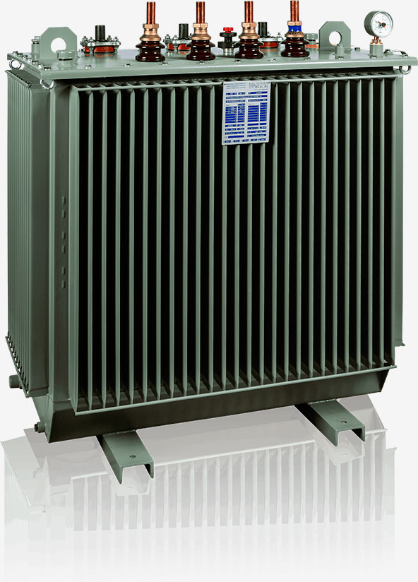
Single-Phase Transformer
The single-phase transformers have a single pair of windings on a single core. These transformers come in various ratings but are primarily used for electronic applications, requiring a smaller amount of power.
Three-Phase transformer
Three-phase transformers are like a group of three single-phase transformers that are coupled together, such that the voltages of each phase have a 120o phase difference between them. These transformers are required for high power rating operations, such as electric power generation, transmission, and distribution systems.
Based on Core
The core design and material can vary the flux density allowed inside the core and, thus, the magnetic flux linkage between the primary and secondary windings of the transformer. In other words, the core can affect the efficiency of transformers. It is, therefore, another important characteristic to classify all transformers. Namely, transformers can have an Iron Core, a Ferrite Core, or an Air Core. A transformer may also have a toroid core design or a solenoid design.
Request A Quote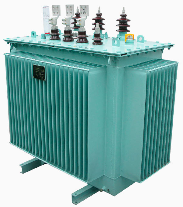
Iron Core Transformers
Iron has good magnetic properties, making it a great choice for core material. Iron cores have high electrical flux density, which is desirable for forming very efficient electrical transformers. A single iron core consists of multiple thin iron plates. Thus, the core can be shaped and sized as required by varying the iron plates' size, shape, and number. Some common iron plate shapes are E, I, U, and L, which can be bunched together to change core design and characteristics as required.
Ferrite Core Transformer
Ferrite is a ceramic-like material with a high magnetic permeability which makes ferrite another excellent material to make into a transformer core. Another benefit of the Ferrite core transformer is that it produces very low losses in high-frequency applications. This is why the ferrite core transformers are the preferred choice of transformers for radio frequency and other switch-mode applications where constant switching signals are used.
Ferrite core transformers come in different shapes and sizes for different application requirements, with the E-core shaped ferrite core transformers being the most common. Ferrite core transformers are more commonly used in electronic applications rather than power system applications.
Air-Core transformer
Air-Core Transformers lack a physical magnetic core. Instead, the flux linkage is performed exclusively through the air. The working principle of Air-Core transformers is the same as that of other transformers - Faraday's Law of Electromagnetic Induction. It states that when an AC voltage is applied to the primary coil, a varying magnetic field is produced in the air around it. When placed within the primary coil's varying magnetic field, the required voltage can be induced in a secondary coil. Thus, power is transferred from one winding to the other. However, the lack of a physical path means very low mutual inductance between the two coils. This makes air-core transformers lighter but also very inefficient compared to iron and ferrite core transformers. The light weight of the air-core transformer makes it suitable for portable electronic and radio frequency applications.
Solenoidal Core Transformer
These are rectangular-shaped and square-shaped core transformers. The leakage of flux around the edges of the closed system causes an increase in the energy losses of the transformer. These transformers have a low cost of production compared to toroidal core transformers and can be used for multi-phase designs and operations. Thus, they are still the most commonly used design for transformer cores.
Toroidal Core Transformer
Toroidal core transformers have a circular-shaped core, increasing the continuity of the magnetic field lines flowing through it. These transformers do not have sharp edges like the solenoidal core transformers. The shape helps reduce the leakage inductance and the associated energy losses. The shape also gives cores with very high Q factors and inductances. Compared to solenoidal transformers of the same ratings, the toroidal core transformer windings are shorter and lighter due to improved efficiency.
Based on Application
Transformers are designed with their application in mind. Thus, transformer application is often used to classify a transformer into one of the four categories: Power, Instrument, Distribution, and Current Transformer.
Request A Quote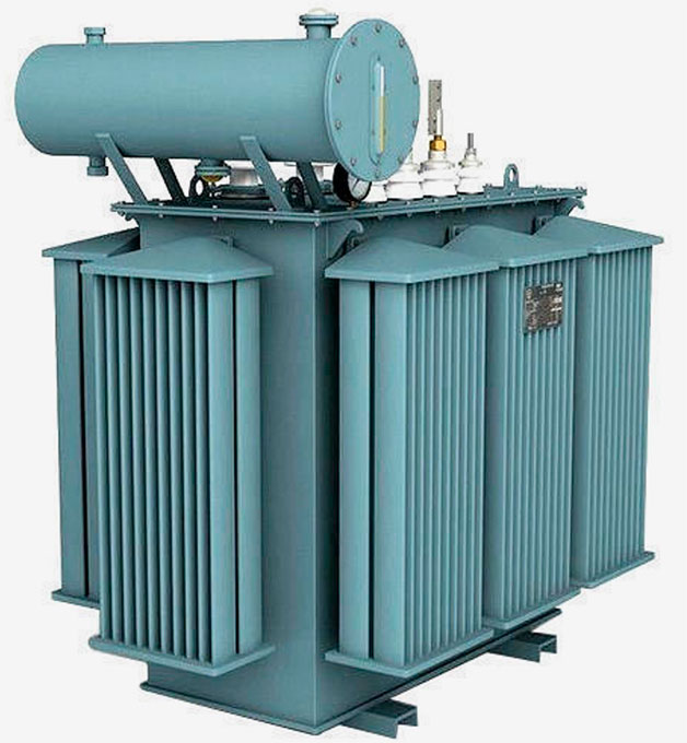
Power Transformers
Power transformers are higher-rated transformers that are exclusively used in power systems to transform low voltage and high current power into high voltage and low current power. The higher voltage and low current power are more suitable for transmission across long distances because of reduced I2R losses in the transmission lines. Thus, these transformers act as a bridge between the power generating and power distribution grids.
Instrument Transformers
Instrument Transformers are also known as measurement transformers and isolation transformers. They change system voltage and current levels to instrument readable standards. Thus, the instrument transformer isolates small measurement equipment, energy meters, and relays to protect them from the power system's high voltage and high currents.
Distribution Transformer
Distribution Transformers are mainly used to change voltage levels in the distribution network of the power system. They are required to lower the voltage level from transmission levels to distribution levels and from distribution levels to household consumption levels. Therefore, these transformers are generally rated at a 200 MVA or lower power capacity and a voltage rating between 230V to 11kV.
The primary coils of a distribution transformer are made of aluminum or enamel-coated copper wire. The secondary winding has a high current and low voltage rating; thus, the winding is made of thick ribbons of aluminum or copper to facilitate the flow of higher currents. The winding insulation is done by using resin-impregnated paper and special insulation oil.
Current Transformer
Current transformers are used to create a lower current reference for sensitive current-measuring instruments to measure the higher currents flowing within the power system. Therefore, current transformers perform two functions: measuring currents and protecting sensitive equipment.
The two terminals of the primary winding of a current transformer are connected in series with the main supply whose current is to be measured. The secondary winding creates a lower value current based on the primary to secondary turn ratio. This current is then fed to measuring instruments like ammeters, voltmeters, etc., to measure the required parameter. The secondary current may also be fed to protective relays to trip the circuit in case of fault current flows in the system. Current transformers are purpose-built to facilitate measurement equipment; thus, they must be highly accurate and have a precise current ratio and phase relation.
Based on Cooling Medium (Dry and Oil Type):
Transformers can also be classified into two categories: Dry-Type Transformers and Oil-Type Transformers, based on the cooling medium used. A dry-type transformer uses air, while an oil-type transformer uses oil to cool down its windings. Oil-type transformers have superior cooling, efficiency, low noise, and a higher voltage rating, but they cannot be used for all applications due to their higher cost, flammability, and toxic nature. On the other hand, dry-type transformers have lower costs, an unlimited supply of coolant (air), are non-flammable, and are non-toxic. These benefits make dry-type transformers more suitable for indoor applications. However, both have their uses and applications.
Request A Quote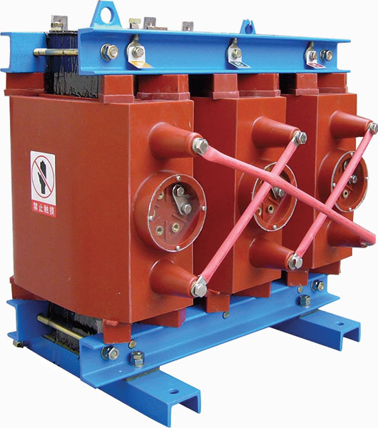
How to Choose the Right Transformer for Your Needs
Choosing the right transformer is critical to ensure efficiency, safety, and longevity in your electrical infrastructure. Whether you're planning for a transformer manufacturing plant or selecting a unit for a commercial facility, this transformer selection guide outlines what you need to know.
Key Considerations in Transformer Selection
Load Requirements: Understand the total connected load in kVA or MVA.
Voltage Levels: Determine both the primary and secondary voltage requirements.
Phase Type: Decide between single-phase or three-phase systems.
Installation Environment: Indoor or outdoor? Harsh weather or corrosive environment?
Cooling Requirements: Dry-type for indoor; oil-type for heavy-duty or outdoor.
Transformer Efficiency & Energy Loss: What You Need to Know
Transformer efficiency directly impacts operational costs and sustainability. By understanding energy loss in transformers, businesses can take steps to reduce waste and improve performance.
Types of Transformer Losses
Core Loss (Iron Loss): Occurs due to alternating magnetic field in the core. Includes hysteresis and eddy current losses.
Copper Loss: Caused by resistance in windings during current flow.
No-Load Loss: Energy lost when the transformer is energized but not supplying load.
Stray & Dielectric Losses: Minor losses due to leakage flux and insulation.
How to Calculate Transformer Efficiency
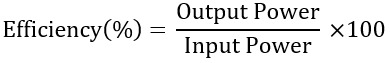
Minimizing losses improves this ratio, especially in high-load scenarios.
How to Reduce Transformer Power Loss
- Use low-loss core materials
- Ensure tight winding construction
- Select high-efficiency transformers for distribution
- Optimize transformer loading and avoid underutilization
Upgrading to energy-efficient transformers pays off over time with lower operational expenses and reduced heat output.
Maintenance and Compliance Guidelines for Industrial Transformers
Industrial transformers are long-term assets that demand regular care to perform efficiently and safely. Whether you're managing a power transformer in a substation or a distribution transformer at an industrial facility, proactive maintenance is essential for reducing downtime, avoiding costly repairs, and ensuring regulatory compliance.
Importance of Power Transformer Maintenance
Power transformers are critical for voltage conversion in transmission networks. Due to their high capacity and continuous load, they are especially vulnerable to thermal and mechanical stresses. A comprehensive power transformer maintenance program ensures operational safety and longevity.
Key areas of focus include:
- Monitoring of core temperature and oil levels
- Regular inspection of bushings and tap changers
- Validation of load balance and grounding
- Ensuring cooling systems (fans or pumps) operate effectively
Transformer Testing and Maintenance Procedures
Routine transformer testing and maintenance ensures early detection of wear or failure and validates electrical performance. Key tests include:
- Insulation Resistance Testing: Verifies the integrity of winding insulation.
- Winding Resistance Test: Detects short circuits, loose connections, or winding degradation.
- Transformer Turns Ratio (TTR) Test: Confirms correct voltage ratios.
- Dissolved Gas Analysis (DGA): Identifies internal faults like arcing or overheating.
- Thermographic Imaging: Detects hotspots caused by poor connections or unbalanced loads.
These tests should be documented as part of your plant's compliance protocol.
Environmental Benefits of Using Energy-Efficient Transformers
As global industries shift toward low-carbon, sustainable operations, energy-efficient transformers have become a vital component of modern power infrastructure. These advanced units are engineered to reduce energy losses, cut carbon emissions, and deliver long-term environmental and economic benefits—without compromising performance.
Whether used in manufacturing plants, utilities, or commercial buildings, high efficiency distribution transformers contribute directly to greener operations and more responsible energy consumption.
The Need for Energy-Efficient Transformers
Transformers run continuously, often for decades. Even minor improvements in their efficiency can significantly impact total energy consumption across an organization or grid. Traditional transformers experience core losses (no-load losses) and copper losses (load losses)—both of which waste energy and increase environmental impact.
By contrast, energy-efficient transformers are designed to:
- Reduce total losses by using optimized materials and design techniques
- Improve performance across a range of loading conditions
- Operate at lower temperatures, enhancing durability and safety
These innovations result in lower electricity demand, reduced fuel consumption at generation plants, and a smaller carbon footprint.
Browse Our Transformers
This page described the different classifications of electrical transformers. These classifications are based on the transformer's voltage operations, phases, winding arrangements, core material, core design, applications, and cooling medium. The different transformers have also been compared to understand their suitability to meet different needs. Some of these transformers are smaller and better suited for electronic applications, while other larger transformers are better suited for power system applications. Finally, it is fascinating to see that the working principle and purpose remain the same regardless of size or application: transfer power at the required voltage and current levels.
View ProductsFrequently Asked Questions
Can I customize a transformer for my specific industrial process?
Yes, many transformer manufacturing plants offer custom-built transformers tailored to meet unique voltage, space, frequency, or environmental requirements. Custom options include special enclosures, winding materials, noise ratings, and cooling systems designed for your specific industry or installation site.
What regulations and standards should my transformer comply with?
Industrial and commercial transformers should comply with standards like ANSI, IEEE C57, NEMA, and DOE energy efficiency requirements. For international use, compliance with IEC 60076 and EU EcoDesign Directive may also be required. These standards ensure safety, efficiency, and reliability under real-world conditions.
Is it possible to monitor transformer health remotely?
Absolutely. Modern transformers can be equipped with smart monitoring systems that track temperature, load, oil condition (for oil-type), and insulation integrity in real-time. These IoT-enabled systems help prevent downtime through predictive maintenance and remote diagnostics.
What safety precautions should be taken when operating a transformer?
Key precautions include grounding the unit properly, keeping clearances as per code, ensuring adequate ventilation or cooling, and avoiding overloads. Always follow lockout-tagout (LOTO) procedures during inspection and servicing. For indoor installations, fire-resistant dry-type transformers are often preferred for added safety.
How does transformer placement affect performance?
Placement matters. Installing transformers too close to heat sources, in poorly ventilated areas, or near vibration-heavy machinery can degrade performance. Outdoor units must be protected from moisture ingress and lightning. Proper placement extends life, reduces energy loss, and minimizes maintenance issues.
What role do transformers play in renewable energy systems?
Transformers are critical in solar and wind energy systems. They step up voltage from inverters for grid compatibility, and isolation transformers are used to separate inverters from the utility grid. For commercial renewable installations, medium-voltage pad-mounted transformers are the norm.
How do harmonics impact transformer performance in commercial buildings?
Non-linear loads like computers, LED lighting, and variable frequency drives generate harmonics—distorted waveforms that increase transformer heating and energy loss. K-rated transformers are specifically designed to handle these harmonic loads without overheating or loss of efficiency.
Can transformers be relocated once installed?
Yes, but it requires careful planning. Relocating a transformer involves de-energizing, draining oil (if applicable), securing windings, and using proper lifting equipment. Site conditions, new load requirements, and grounding systems must also be reviewed before recommissioning.
How do I determine transformer capacity for expanding operations?
Conduct a transformer sizing analysis by reviewing your total load (kVA), future expansion plans, and load diversity. Oversizing wastes energy and increases costs, while undersizing causes overheating and voltage drops. A qualified engineer or supplier can help with capacity modeling.