
What are Electrical Transformers?
Transformers are static electromagnetic devices that can change electrical signals’ voltage and current magnitudes without changing the signal power and frequency. Transformers are used to improve the safety and efficiency of electric power systems by decreasing or increasing the voltage of the signal to desired levels. This article discusses the operating mechanism, functional types, key components, and applications of a transformer device.
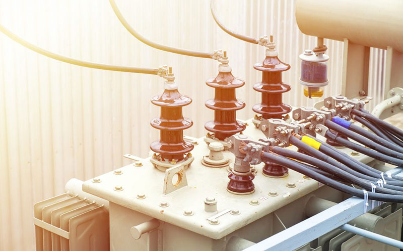
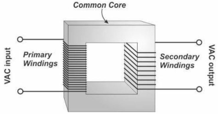
Figure. Electrical Transformer:
How do transformers work?
Transformer operation can be described by the Law of Energy Conservation, which states that “energy can neither be created nor destroyed but can only be transformed from one form to another”. A transformer adheres to this fundamental law of our universe as it does not make any new electrical energy but merely changes the voltage of existing electrical energy, as required, through electromagnetic induction between two conductor coils.
Electromagnetic Induction
When an alternating electric current is passed through a conductor wire, an alternating magnetic field is formed around it. If a second conductor wire is
placed within this magnetic field, the moving flux lines will cut the second wire and induce a voltage in it. Electromagnetic induction can decrease or increase the voltage induced in the second wire by making physical changes to the two conductor wires. If the two conductors are wrapped into coils, and one conductor has a longer length than the other, then the longer coiled conductor will have more loops. If this longer conductor is energized with an alternating electric current, the shorter second conductor will have less voltage induced due to fewer loops. This relationship can be reversed by lowering the length of the energized conductor compared to the second conductor.
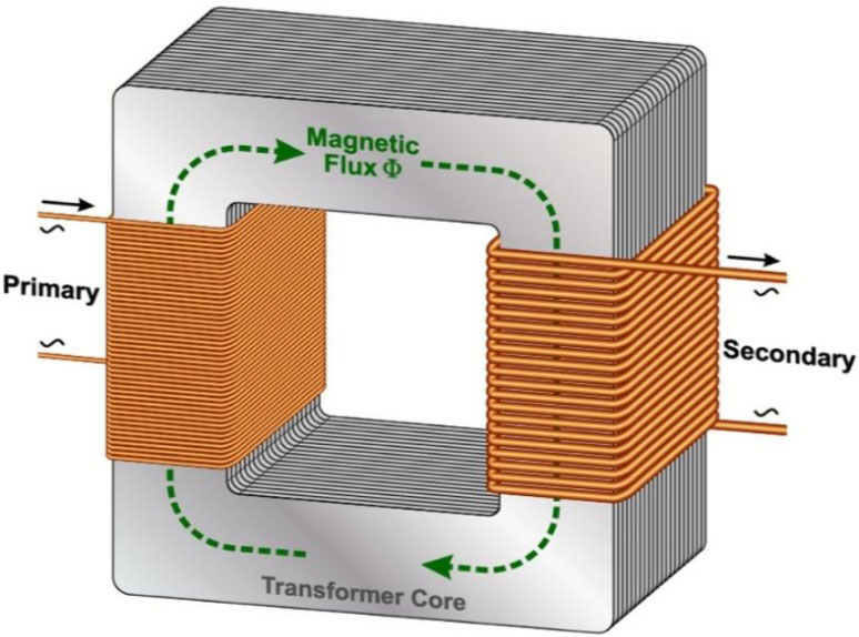
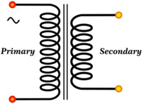
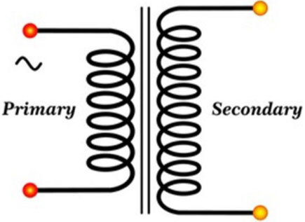
In the case of a transformer device, the first conductor energized by an outside source is known as the primary coil or primary winding, whereas the second conductor on which the voltage is induced is known as the secondary coil or secondary winding. Each loop in the coil is called a “turn”. These two coils are made of copper or aluminum and are wrapped around an iron core to ensure maximum magnetic linkage between the two coils.
How does a transformer give exact voltages?
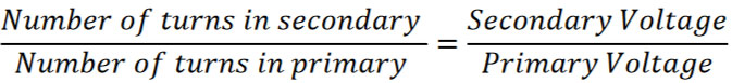
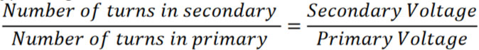
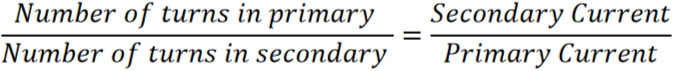
The ratio of voltage between the primary and secondary coils depends directly on the ratio of turns between the two coils. To achieve the precise voltage you require, it is necessary to construct a transformer with an exact desired ratio of turns in each coil.
Figure. Transformer Primary and Secondary Coils:
Voltage in a transformer can be altered in two ways: It can be either stepped up or stepped down, depending on the specific requirements.
Step-down Transformers
If the primary coil of the transformer has more turns than the secondary coil, the secondary coil will have a lower voltage induced on it. This will result in a smaller output voltage than the applied voltage. A transformer that performs the function of reducing voltage is referred to as a step-down transformer.
Figure. Diagram of a Step-Down Transformer
In general, the lower output (secondary) voltage of the step-down transformer can be calculated by using the following formula:
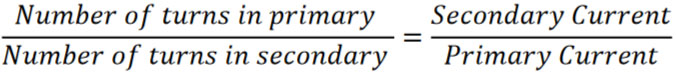
Voltage transformation is accompanied by current transformation. When voltage is transformed, the current will go through the opposite transformer action increased in size for a step-down transformer. This output (secondary) current can be calculated by using the following formula:
For example, if the primary winding of a transformer has 100 turns and the secondary winding has 10 turns, then the two windings will have a turns ratio of 100:10 or 10:1. If the primary winding is energized with a voltage of 500 volts, the step-downtransformer action will yield an output voltage of 50 volts on the secondary winding. Thus, a step-down transformer with a 10:1 turns ratio will step down the voltage by a factor of 10. However, the current will be stepped up by the same factor and will result in a 10 Amps current in the secondary winding for every 1 Amp current in the primary winding.
The power of an electric signal is equal to the product of the signal voltage and current (watts = volts x amps). Theoretically, the secondary power remains the same as in the primary coil. However, some power loss occurs due to various transformer losses, e.g., flux, iron, copper, Hysteresis, and eddy current losses.
Step-up transformers
A step-up transformer is simply a reverse of the step-down transformer as it increases the voltage of an incoming electrical signal by the turns-ratio factor and reduces its current by the same factor. This action is performed because there are a greater number of turns in the secondary winding as compared to the primary winding.
Figure. Diagram of a step-up transformer
The following expressions can be used to calculate the resulting stepped-up output (secondary) voltage and stepped-down output (secondary) current for known values of input (primary) voltage and current:
and,
Considering both transformers, we can come up with a general rule to understand transformer actions: “The coil that has more turns will have the higher voltage of the two coils, and the coil with the fewest turns will have the highest current of the two coils”.
Isolation transformer
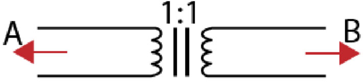
Isolation transformers are special-purpose transformers used to electrically and physically isolate two circuits while transferring voltage and current signals between them. They do not perform any step-up or step-down actions on the incoming voltage signal because these transformers have a turn ratio of 1:1. These transformers simply transfer the incoming electrical signal to the secondary circuit.
Suppose we want to isolate circuit A from circuit B, as shown in the figure below. We must connect the primary and secondary windings of the isolation transformer to circuits A and B, respectively. Supplying an electrical signal on the primary side would create an equal signal on the secondary side through mutual induction. Thus, electrical energy will be transferred between the two circuits through electromagnetic induction between the two coils of the isolation transformer without any physical or electrical path. Transformers are typically used in devices, including televisions, computers, industrial- sensitive electronic devices, and solid-state circuits.
Figure. An isolation transformer connecting Circuit A and Circuit B
Parts of a Transformer
A transformer consists of various components, each contributing differently to the performance of the transformer. The core, windings, tap changer, insulating materials, transformer oil, tank, bushings, and gauges are among the primary components.
Bushings
Transformer bushings are insulated terminals that are present on the external surface of the transformer. They are the external connection points to the transformer windings inside the transformer tank that can be accessed safely without making electrical contact with the transformer tank walls. Transformer bushings connect the power source on the primary (HV) windings and the load on the secondary (LV) windings of the transformer.
Tank
The transformer tank houses the oil, providing physical support and protection to the transformer’s various components and grounding the magnetic circuit and various metal parts.
Tank bodies are produced by molding rolled steel plates into containers and installing lifting hooks and cooling tubes. In some cases, aluminum sheets may be used instead of steel plates to reduce the transformer’s weight and prevent stray losses.
Core
The transformer core not only supports the transformer windings physically but also provides a path of low reluctance to facilitate the flow of magnetic flux between the two windings. A transformer core typically comprises laminated soft-iron material to reduce Hysteresis and eddy current loss. Voltage, current, and frequency are important factors in determining the required composition of a transformer core. The size of the transformer core has a direct relationship with core loss and an inverse relationship with copper loss. By increasing the size of the core, the weight of the steel within the core is also increased, resulting in higher core losses for the transformer while decreasing copper losses. Conversely, reducing the size of the core yields the opposite effect.
Load-break switches
Transformer load-break switches are special rotary switches that can be triggered by electrical workers to manually disconnect a transformer from its power grid and ensure that the transformer coils and core are completely de-energized. As the name “load- break switches” suggests, these switches can be used even when the transformer is “under load”.
Fuses
A transformer fuse protects electrical systems from overcurrent faults and problems within the transformer or downstream equipment. When subjected to a dangerously high current or excessive heat, a thin wire referred to as an “element” inside the fuse melts. This leads to the interruption or discontinuation of the electricity flow, effectively disconnecting the transformer from the utility grid.
Tap Changer
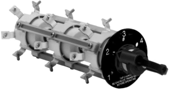
The output voltage of a transformer can vary with changes in the input voltage on its primary side and the connected load on its secondary. The output voltage decreases during loaded conditions and increases during off-load conditions. These variations are balanced with the help of special devices known as tap changers, which change the effective turns ratio of a transformer by changing tap positions. This helps us vary the voltage applied to the connected load on the secondary winding for different conditions. Some tap changers, known as on-load tap changers, can be operated without isolating the transformer from the supply. Other tap changers, known as off- load tap changers, require the transformer to first be disconnected and de-energized before changing the tap positions. Certain tap changers are automatic, while others require manual operation.
Figure. Transformer taps Changer:
Insulating Material
Transformers typically use three main insulating materials: mineral oil, paper, and pressboard in various forms. Current flow in transformer windings causes the transformer to heat up, and its operational efficiency becomes increasingly dependent on how well the transformer is cooled down during use. Some transformers, known as liquid-filled transformers, have a special fluid-filled tank that uses channels known as “ducts” to pass fluid between the transformer windings. This fluid acts as an insulator and a cooling medium, thus regulating the electrical and thermal properties of the windings and maintaining low temperatures within the transformer.
The paper material is used to insulate the winding turns, while the pressboard is utilized to reinforce electrical insulation and provide dielectric spacing at specific locations, such as in the primary duct between the windings.
Gauges
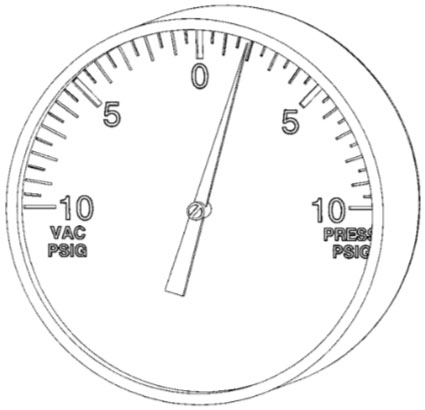
Gauges are installed on a transformer to monitor the various operating conditions of the transformer, such as tank pressure, oil level, and temperature. In larger transformers, more sophisticated monitoring strategies and equipment are employed.
Figure. Pressure Vacuum Gauge:
Winding
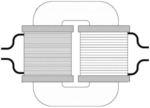
A transformer typically has two sets of windings placed around the transformer core and kept insulated from each other. These windings are electrically and physically separated from each other but magnetically linked through the core. Windings can be classified in two different ways based on the input/output supply and their voltage range.
Based on the input/output supply, windings can be classified as:
- Primary winding – These windings are used to apply the input voltage signal to the transformer.
- Secondary winding – These windings are used to derive the output voltage signal from the transformer after the transformer action is performed on the input signal.
Based on their voltage range, windings are further categorized as:
- Low voltage windings – These windings have fewer turns of thick copper conductors. The conductor is thicker to allow larger currents to flow than in high-voltage windings.
- High voltage windings – These windings have more turns of thin copper conductors. The number of turns in high-voltage windings is designed as the multiple of the number of turns in low-voltage windings. High-voltage windings use thinner conductors than low-voltage windings because less current flows through them.
Input supply can be applied on either of the two transformer terminals (LV or HV) based on the required transformer action (step-up or step-down).
Figure. Transformer Primary and Secondary Windings:
Transformer Applications
- Step-up transformers are installed at power-generating stations to increase the voltage of the outgoing electrical power. This helps lower the amount of current that needs to be transmitted over long distances and, thus, helps reduce transmission line losses.
- Step-down transformers are installed at substations where high voltage is transformed to distribution system low voltages. Step-down transformers are also used in various home appliances and inverters.
- Transmission lines have very high voltages and currents that cannot be directly measured through voltmeters and ammeters. Therefore, special instrument transformers like voltage and current transformers are used to measure them instead.
- Single-phase transformers are used for low-power applications like powering up commercial and residential devices.
- Three-phase transformers are used for high-power applications. They are primarily used in power generation and distribution network applications. They are also used to feed high-power industrial loads such as rectifiers, motor drives, and other equipment.
Key Takeaways
- Transformers are static electromagnetic devices that can transfer electrical energy from one circuit to another without varying the frequency of the signal.
- Transformers are designed and operated based on the principle of Faraday’s Law of Electromagnetic Induction.
- All transformers consist of a primary winding, a secondary winding, and a core. The voltage of the input signal is dependent on the turn’s relation between the primary and secondary windings. The equation VP/ VS = NP/NS determines the relationship between the number of turns and voltage in the primary and secondary windings.
- Different components may be installed on the transformer to facilitate the transformer functions. These components include gauges, bushings, tap changers, fuse, insulating materials, transformer tank, and load brake switches.
- Transformers can be classified based on the construction of their cores and windings, number of phases, core material, and turn ratios.
- Copper loss, flux loss, eddy current loss, and hysteresis loss reduce the overall efficiency of transformers.