
What is a Transformer Vector Group?
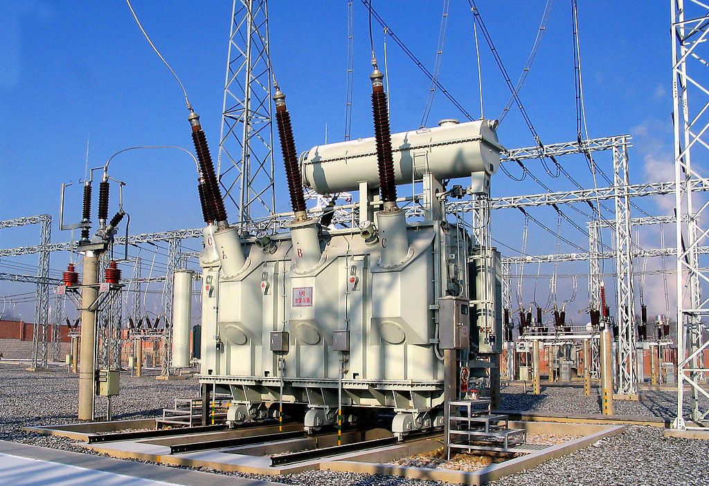
AC voltage is applied to the transformer’s primary coil, causing a current to flow through it. This coil is wound around an iron core, which provides a path for the flow of a changing magnetic flux. The changing magnetic flux induces a voltage on a secondary coil wound around the iron core. The secondary voltage phase depends on how the coils are wound around the core. The induced voltage may be in-phase or 180o out of phase of the primary voltage.
A three-phase transformer has more coils wound around the core, one for each winding. Thus, there are more options for how to connect the windings. The connection type changes the phase relationship between the two voltages.
Three-Phase Transformer Configurations
A three-phase transformer has three primary and secondary windings, each wound around an iron core, making three sets for the three-phase power that must flow through the transformer. This same setup can be realized by externally connecting three different single-phase transformers’ windings. The windings on each side, primary and secondary, can be connected in delta and star configurations.
In the delta configuration, the polarity end of a winding is connected to the non-polarity end of another winding. This gives a closed ring connection between the three windings. Phases are taken from the common coupling points between the windings.
In the star configuration, all windings’ non-polarity ends are connected to form a neutral point. The polarity ends of the windings are taken as the phase terminals.
We can get a total of four configurations by varying the primary and secondary winding connections. For example, if the primary winding of a transformer is configured in a star connection, the secondary winding might have the same configuration (star) or different (delta). The different connections can yield transformers with delta-delta, star-star, delta-star, and star-delta configurations.
With similar primary and secondary winding configurations (star-star and delta-delta), the secondary voltage waveform is completely in phase with the primary waveform. This is called the “no phase shift” condition.
With different primary and secondary winding configurations (star-delta and delta-star), the secondary voltage waveform is 30o out of phase with the primary waveform, and the condition is called a 30-degree phase shift. This condition presents a problem when connecting two three-phase transformers in parallel. In such cases, it is important to ensure that there is no relative phase difference between the secondary voltage waveforms of the two transformers. Otherwise, a short circuit would occur whenever the transformers are energized.
Winding connection designations using Vector Groups
From the above section, it is important to understand the connections of the internal coils of a three-phase transformer. The International Electrotechnical Commission (IEC) introduced Vector Groups to solve the classification issue for three-phase transformers. Vector Groups are used to designate winding connection information for the two windings (low-voltage and high-voltage) and the phase relationship between them.
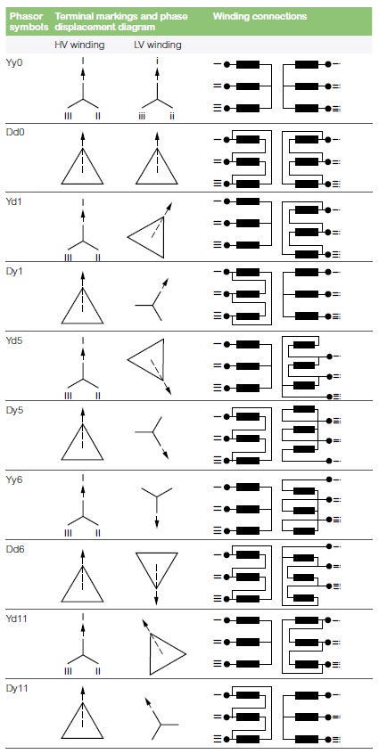
Figure 1: Vector Groups of Three-phase Transformers:
Phase Displacement between HV and LV Windings
Vector groups provide information about the winding configurations and phase relationships of the two windings. The configuration aspect is very simple; however, knowing how to use the vector group symbol to find the phase displacement between the windings is important.
The high-voltage winding vector is used as the reference vector to find the phase displacement on the low-voltage side. The angle displacement between the two vectors through the anticlockwise rotation is taken in clock-hour figures in the vector groups to describe phase displacement between the windings.
Following the IS 2026 (Part 1V)-1977 standard, there are 26 sets of connections star-star, star-delta, star-zigzag, delta-delta, etc. Displacement of the low voltage winding vector varies from zero to -330° in steps of -30°, depending on the method of connections. However, it is uncommon that the full 26 sets are utilized. Most transformers are connected, so they introduce phase shifts of 0, -30, -180, and -330 degrees that correspond to the clock-hour notations of 0, 1, 6, and 11, respectively. The different hand clock positions are taken with the High-voltage winding vector at the 0-hour position. The following Low voltage vector positions mean:
- Digit 0 = Both winding vectors are in phase.
- Digit 1 = LV vector is lagging the HV vector by 30°.
- Digit 5 = LV vector is lagging the HV vector by 150°.
- Digit 6 = LV vector is lagging the HV vector by 180°.
- Digit 11 = LV vector is lagging the HV vector by 330°.
The formula “30 x Clock Handle Value” can be used to find the phase displacement between the two windings. Now, let’s take one of the phasor symbols in Figure 1 as an example for finding the type of winding configurations used, and the phase displaced.
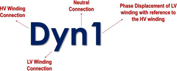
Example – Dyn1
The following rules are used to analyze a vector group to identify a transformer device.
- The first symbol is always a capital letter, describing the high-voltage side’s winding configuration. The symbol can be D, S, Z, or N, meaning that the high voltage winding is in Delta, Star, Interconnected star, or Neutral configuration.
- The second symbol is always a small letter, describing the low-voltage side’s winding configuration. The symbol can be d, s, z, or n, which means that the high voltage winding is in Delta, Star, Interconnected star, or Neutral configuration, respectively.
- The third symbol represents the phase displacement between the two windings and is expressed in terms of the clock hour number (1, 6, 11).
- An additional symbol, namely n, is added to show that the neutral connection is taken out from the star-connected side.
Using these rules , we see that the transformer in this particular example (vector group = Dyn1) must have a delta-connected high-voltage winding ( D ), a star-connected low-voltage winding ( y ) with the star point brought out ( n ), and a 30o lagging phase shift as power goes from the high-voltage side to the low-voltage side ( 1 ). This means that this is a delta-star transformer. The breakdown is shown in figure 2.
Figure 2: Vector Group symbol breakdown:
For additional windings, for example, a 220/66/11 kV star-star-delta transformer, the winding information can be represented in the vector group by using symbols of the windings in diminishing voltage sequence. This means that the vector group should be divided into two sections for a 220/66 kV star-star configuration and a 220/11 kV star-delta configuration, both referring to the same High voltage vector of 220kV star winding. The resultant vector group in this scenario would be Yy0 – Yd11; Yy0 (star-star, so no phase displacement), Yd11 (The delta LV winding has a 330-degree lag or a 30-degree lead). Different vector groups and phase shifts are shown in Table 1.
Table 1

When connecting two three-phase transformers in parallel, it is important to know the vector groups of the two transformers. Transformers should only be connected if they have the same vector groups. Otherwise, large circulating currents would flow between the secondary windings of the two transformers upon energizing the transformers.
The manufacturer indicates the vector group for a three-phase transformer on the transformer nameplate for quick and easy determination of the transformer characteristics. We can quickly identify the transformer configuration by looking up its nameplate and finding the appropriate phasor symbol, as shown in Figure 1.
Transformers that follow the ANSI standards may not have such vector groups and instead display a vector diagram relationship of the windings and phases.
Key Takeaways
The IEC method introduces vector groups for categorizing the three-phase transformer winding configurations. Windings may be connected in delta, star, or zigzag. The polarity of the windings is also important because it affects their phase relationship. All of this information can be easily provided through vector groups. Always make sure to study them on transformer nameplates before connecting the transformer to the power system.